


Chapter 3 Interrupts
III - 50
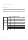
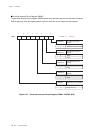
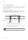
External Interrupts
If there is at least one input signal, from the P60 to P63 pins, shows low level, the external interrupt
4 is generated at the falling edge.
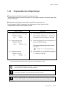
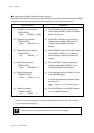
■Key Input Interrupt Setup Example (External interrupt 4)
After P60 to P63 of port 6 are set to key input pins and key is input (low level), the external interrupt 4 (IRQ4)
is generated. An example setup procedure, with a description of each step is shown below.
(1) Set the P6DIR3-0 flag of the port 6 direction
control register (P6DIR) to "0000" to set P60 to
P63 pins to input pins.
(2) Set the P6PLU 3-0 flag of the port 6 pull-up
resistance control register (P6PLU) to"1111"
to add the pull-up resistance to P60 to
P63 pins.
(3) Set the IRQ4SEL flag of the port 6 key interrupt
control register (P6IMD) to "1" to select the
external interrupt 4 source to the port 6 key
interrupt.
(4) Set the P6KYEN 2-1 flag of the port 6 key
interrupt control register (P6IMD) to "11" to
set P60 to P63 pins to key input pins.
(5) Set the interrupt level by the IRQ4LV1-0 flag
of the IRQ4ICR register.
If the interrupt request flag has been already
set, clear the it.
[ Chapter 3 3-1-4. Interrupt flag setup ]
(6) Set the IRQ4IE flag of the IRQ4ICR register
to "1" to enable the interrupt.
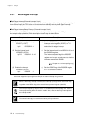
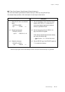
Setup Procedure
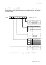
(1) Set the key input pin to input.
P6DIR (x'3F36')
bp3-0 : P6DIR3-0 = 0000
(2) Set the pull-up resistance.
P6PLU (x'3F46')
bp3-0 : P6PLU3-0 = 1111
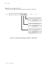
(3) Select the key input interrupt.
P6IMD (x'3F3E')
bp7 : IRQ4SEL = 1
(4) Select the key input pin.
P6IMD (x'3F3E')
bp1-0 : P6KYEN2-1= 11
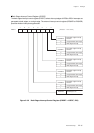
(5) Set the interrupt level.
IRQ4ICR (x'3FE6')
bp7-6 : IRQ4LV1-0= 10
(6) Enable the interrupt.
IRQ4ICR (x'3FE6')
bp1 : IRQ4IE = 1
Description
Note : The above (3) and (4) are set at the same time.
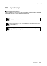
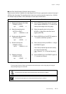
The setup of the key input should be done before the interrupt is enabled.