


Chapter 12 Serial Interface 3
Operation
XII - 24
13-3-2 Setup Example
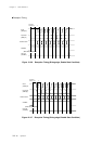
Transmission/Reception Setup Example
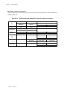
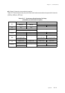
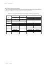
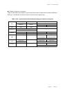
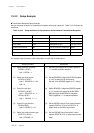
Here is the setup example for transmission/reception with serial interface 3. Table 12-3-10 shows the
conditions.
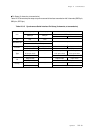
Table 12-3-10 Setup conditions for Synchronous Serial Interface Transmission/Reception
Description
(1) Set the PSCEN flag of the PSCMD register to
"1" to select prescaler operation.
(2) Set the SC3PSC2-0 flag of the SC3CKS register
to "100" to select fs/2 at clock source.
Set bp3 of the SC3CKS register to "0", always.
(3) Set the SC3ODC1-0 flag of the SC3ODC register
to "11" to select N-ch open drain for the SBO3/
SBT3 pin's type. Set the P5PLU2-1 flag of the
P5PLU register to "1, 1" to add pull-up resistor.
(4) Set the P5DIR2-0 flag of P5 pin control direction
register (P5DIR) to "110" to set P52, P51, to
output mode, to set P50 to input mode.
(5) Set the SC3CMD flag of the serial 3 control
register (SC3CTR) to "0" to select synchronous
serial.
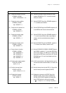
An example setup procedure, with a description of each step is shown below.
Setup Procedure
(1) Select prescaler operation.
PSCMD (x'3F6F')
bp0 : PSCEN = 1
(2) Select the clock source.
SC3CKS (x'3FAF')
bp2-0 : SC2PSC2-0 = 100
bp3 = 0
(3) Control the pin type.
SC3ODC (x'3FAE')
bp1-0 : SC3ODC1-0 = 11
P5PLU (x'3F45')
bp2, 1 : P5PLU2, 1 = 1, 1
(4) Control the pin direction.
P5DIR (x'3F35')
bp2-0 : P5DIR2-0 = 110
(5) Select the communication type.
SC3CTR (x'3FAA')
bp2 : SC3CMD = 0
Item Set to Item Set to
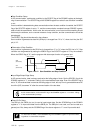
SBI3/SBO3 pin independent (with 3 lines) Clock internal clock
Transfer bit count 8 bits Clock source fs/2
Start condition enable SBT3/SBO3 pin type N-ch open-drain
First bit to be transfered MSB Pull-up resistance of SBT3 pin added
Input edge at falling Pull-up resistance of SBO3 pin added
Output edge at rising