


VI - 31
Chapter 6 8-bit Timers
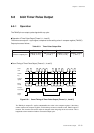
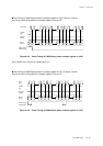
Synchronous Output
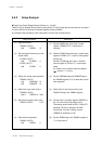
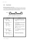
6-7-2 Setup Example
Synchronous Output Setup Example (Timer 1, Timer 5)
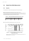
Setup example that latch data of port 6 is output constantly (100 µs) by using timer 1 from the synchronous
output pin is shown below. The clock source of timer 1 is selected fs/8 (at fosc=8 MHz).
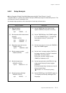
An example setup procedure, with a description of each step is shown below.
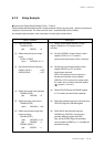
(1) Set the TM1EN flag of the timer 1 mode
register (TM1MD) to "0" to stop the timer 1
counting.
(2) Set the SYOEVS1-0 flag of the pin control
register (FLOAT) to "11" to set the
synchronous output event to timer 1 interrupt.
(3) Set the port 6 synchronous output control
register (P6SYO) to x'FF' to set the
synchronous output pin.
(P67 to P60 are synchronous output pin.)
Set the port 6 direction control register
(P6DIR) to x'FF' to set port 6 to output mode.
If it needs, pull up resistor should be added.
(4) Set the TM1CAS flag of the TM1MD register
to "0" to select the normal timer operation.
(5) Select the prescaler output for clock source by
TM1CK2-0 flag of the TM1MD register.
(6) Select fs/8 for the prescaler output by
TM1BAS flag, TM1PSC1-0 of the timer 1
prescaler selection register (CK1MD).
Also, set the PSCEN flag of the prescaler
control register (PSCMD) to "1" to enable the
prescaler counting.
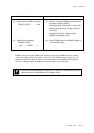
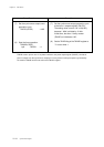
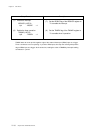
Setup Procedure
(1) Start the counter.
TM1MD (x'3F55')
bp3 :TM1EN = 0
(2) Select the synchronous output
event.
FLOAT (x'3F2E')
bp1-0 :SYOEVS1-0 = 11
(3) Set the synchronous output pin.
P6SYO (x'3F1E') = x'FF'
P6DIR (x'3F36') = x'FF'
(4) Select the normal timer operation.
TM1MD (x'3F55')
bp4 :TM1CAS = 0
(5) Select the count clock source.
TM1MD (x'3F55')
bp2-0 :TM1CK2-0 = 001
(6) Select the prescaler output and
enable counting.
CK1MD (x'3F57')
bp2-1 :TM1PSC1-0 = 01
bp0 :TM1BAS = 1
PSCMD (x'3F6F')
bp0 :PSCEN = 1
Description
[ Chapter 4. I/O Ports ]