


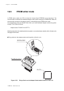

Chapter 18 Flash EEPROM
XVIII - 8
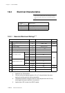
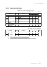
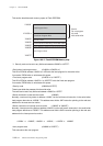
Electrical Characteristics
*1 - Measured under conditions of no load, or power down on analog blocks. (Pull-up resistance
should be unconnected.)
- The supply current during operation, IDD1 (IDD2) are measured under the following condi-
tions :
After all I/O pins are set to input mode and the oscillation is set to <NORMAL mode>,
the MMOD pin is at VSS level, the input pins are at VDD level, and a 20 MHz(8.39 MHz)
square wave of VDD and VSS amplitudes is input to the OSC1 pin.
- The supply current during operation, IDD3, is measured under the following conditions :
After all I/O pins are set to input mode and the oscillation is set to <SLOW mode>, the
MMOD pin is at VSS level, the input pins are at VDD level, and a 32 kHz square wave of
VDD and VSS amplitudes is input to the XI pin.
- The supply current during HALT mode, IDD4, are measured under the following conditions :
After all I/O pins are set to input mode and the oscillation is set to <HALT mode>, the
MMOD pin is at VSS level, the input pins are at VDD level, and an 32 kHz square wave of
VDD and VSS amplitudes is input to the XI pin.
- The supply current during STOP mode, IDD5 (IDD6) are measured under the following condi-
tions :
After the oscillation is set to <STOP mode>, the MMOD pin is at VSS level, the input pins are
at VDD level, and the OSC1 and XI pins are unconnected.
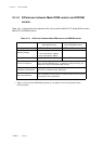
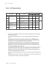
18-3-3 DC Characteristics
Ta =
−
40
o
C to
+
85
o
C V
DD
= 3.3 V V
SS
= 0 V
MIN TYP MAX
1I
DD1
fosc=20.0 MHz, fs=focs/2
V
PP
=V
DD
=3.3 V
-1124
2I
DD2
fosc=8.39 MHz, fs=focs /2
V
PP
=V
DD
=3.3 V
-5.511
3I
DD3
fx=32 kHz, fs=fx/2
V
PP
=V
DD
=3.3 V
-100160
4
Supplu current during
HALT1 mode
I
DD4
fx=32 kHz, V
PP
=V
DD
=3.3 V - 80 160
5I
DD5
V
PP
=V
DD
=3.3 V Ta=
+
25
o
C
-02
6I
DD6
V
PP
=V
DD
=3.3V
Ta= -40
o
C to +25
o
C
--40
Supply current during
STOP mode
mA
µ
A
Rating
Parameter Symbol Conditions
Power supply current
Power supply current (no load at output pin) *1
Unit