


VI - 15
Chapter 6 8-bit Timers
8-bit Timer Count
6-3 8-bit Timer Count
6-3-1 Operation
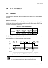
The timer operation can constantly generate interrupts.
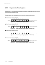
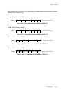
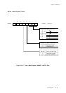
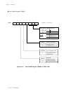
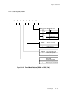
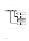
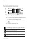
8-bit Timer Operation (Timers 0, 1, 4 and 5)
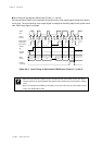
The generation cycle of timer interrupts is set by the clock source selection and the setting value of the
compare register (TMnOC), in advance. If the binary counter (TMnBC) reaches the setting value of the
compare register, an interrupt is generated at the next count clock, then binary counter is cleared and
counting is restarted from x'00'.
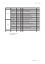
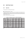
Table 6-3-1 shows clock source that can be selected.
Table 6-3-1 Clock Source (Timers 0, 1, 4 and 5) at Timer Operation
Clock source 1 count time
Ti mer 0
(8 Bit)
Ti mer 1
(8 Bit)
Ti mer 4
(8 Bit)
Ti mer 5
(8 Bit)
fosc 50 ns
√√√√
fosc/4 200 ns
√√√√
fosc/16 800 ns
√√√√
fosc/32 1.6 µs
√
-
√√
fosc/64 3.2 µs
√√√√
fosc/128 6.4 µs -
√
--
fs/2 200 ns
√√√√
fs/4 400 ns
√
-
√√
fs/8 800 ns -
√
--
fx 30.5 µs
√√√√
Notes : as fosc = 20 MHz fx = 32.768 kHz fs = fosc/2 = 10 MHz