Chapter 2 CPU Basics
II - 38
Reset
2-8 Reset
2-8-1 Reset operation
The CPU contents are reset and registers are initialized when the NRST pin is pulled to low.
Initiating a Reset
There are two methods to initiate a reset.
(1) Drive the NRST pin low.
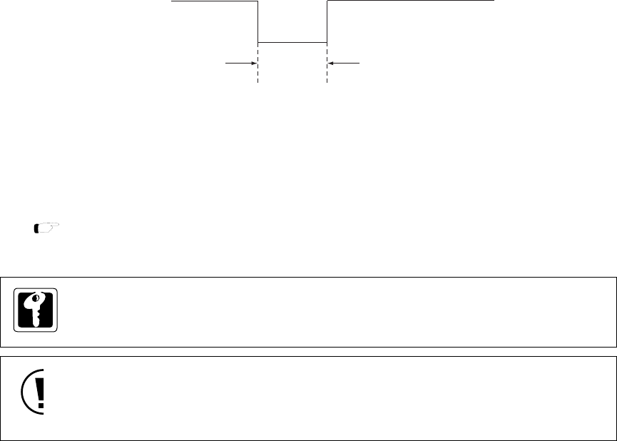
NRST pin should be held "low" for more than OSC 4 clock cycles (200 ns at 20 MHz).
Figure 2-8-1 Minimum Reset Pulse Width
(2) Setting the P2OUT7 flag of the P2OUT register to "0" outputs low level at P27 (NRST) pin. And
transferring to reset by program (software reset) can be executed. If the internal LSI is reset
and register is initiated, the P2OUT7 flag becomes "1" and reset is released.
NRST pin
4 clock cycles
(200 ns at 20 MHz)
[ Chapter 4. 4-4-2 Registers ]
On MN101C77 series, the starting mode is NORMAL mode that high oscillation is the base
clock.
When NRST pin is connected to low power voltage detection circuit that gives pulse for
enough low level time at sudeen unconnected. And reset can be generated even if NRST pin
is held "low" for less than OSC 4 clock cycles, take notice of noise.


