


XI - 41
Chapter 11 Serial Interface 0, 1
Operation
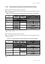
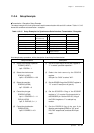
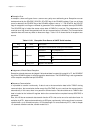
(15) Set the interrupt level.
SC0TICR (x'3FF5')
bp7-6 : SC0TLV1-0 = 10
(16) Enable the interrupt.
SC0TICR (x'3FF5')
bp1 : SC0TIE = 1
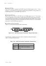
(17) Start serial transmission.
Transmission data→TXBUF0 (x'3F91')
Received data→input to SBI0A pin.
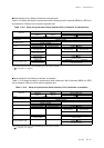
(15) Set the interrupt level by the SC0TLV1-0 flag of
the serial 0 transmission interrupt control register
(SC0TICR). (Set level 2.)
(16) Set the SC0TIE flag of the SC0TICR register to
"1" to enable interrupts.
If any interrupt request flag (SC0TIR of the
SC0TICR register) is already set, clear SC0TIR
before an interrupt is enabled.
(17) Set the transmission data to the serial
transmission data buffer TXBUF0. Then, an
internal clock is generated to start transmission /
reception. After the transmission is finished,
serial0 transmission interrupt SC0TIRQ is
generated.
Note : In (6) to (9), (10) to (11), (12) to (14),each settings can be set at once.
[ Chapter 3 3-1-4. Interrupt Flag Setup ]
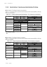
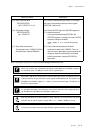
When only reception with 3 channels is operated, set SCnSBOS of the SCnMD1 register to
"0" and select a port. The SBO pin can be used as a general port.
When SBO / SBI pin are connected for communication with 2 lines, the SBO pin inputs /
outputs serial data. The port direction control register PnDIR switches I/O. At reception, set
SCnSBIS of the SCnMD1 register to "1", always, to select "serial data input". The SBI pin can
be used as a general port.
It is possible to shut down communication. If the communication should be stopped by force,
set SCnSBOS and SCnSBIS of the SCnMD1 register to "0".
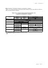
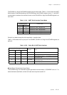
Each flag should be set as the procedure in order. Activation for communication should be
operated after all control registers (except Table 11-2-1 : TXBUFn, RXBUFn) are set.
Transfer rate of transfer clock that set by SCnCKS register should be under 2.5 MHz.
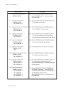
Setup Procedure Description