


Chapter 8 Time Base Timer / 8-bit Free-running Timer
VIII - 14
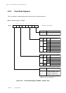
Time Base Timer
Timer Operation Setup (Time Base Timer)
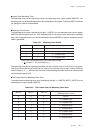
An interrupt can be generated constantly with time base timer in the selected interrupt cycle. The inter-
rupt generation cycle is as fosc × 1/2
13
(as 0.977 ms : fosc = 8.38 MHz) for generation interrupts.
An example setup procedure, with a description of each step is shown below.
(1) Select fosc as a clock source by the TM6CK0
flag of the timer 6 mode register (TM6MD).
(2) Select the selected clock × 1/2
13
as an interrupt
generation cycle by the TM6IR2-0 flag of the
TM6MD register.
(3) Write value to the time base timer clear control
register (TBCLR) to initialize the time base
timer. That makes the time base timer initialize.
(4) Set the interrupt level by the TBLV1-0 flag of
the time base interrupt control register
(TBICR).
If the interrupt request flag had already been
set, clear it.
(5) Set the TBIE flag of the TBICR register to "1"
to enable the interrupt.
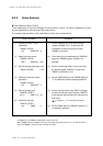
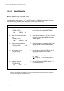
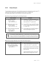
Setup Procedure
(1) Select the clock source.
TM6MD (x'3F6A')
bp0 : TM6CK0 = 0
(2) Select the interrupt generation
cycle.
TM6MD (x'3F6A')
bp6-4 : TM6IR2-0 = 100
(3) Initialize the time base timer.
TBCLR (x'3F6B') = x'00'
(4) Set the interrupt level.
TBICR (x'3FF0')
bp7-6 : TBLV1-0 = 01
(5) Enable the interrupt.
TBICR (x'3FF0')
bp1 : TBIE = 1
Description
8-4-2 Setup Example
When the selected interrupt generation cycle has passed, the interrupt request flag of the time base
interrupt control register (TBICR) is set to "1".
* the above steps (1), (2) can be set at once.
[ Chapter 3 3-1-4. Interrupt Flag Setup ]