


Chapter 7 16-bit Timer
VII - 38
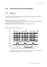
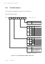
16-bit Timer Capture
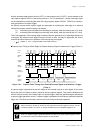
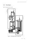
TM7BC counts up from x'0000'. At the timing of the rising edge of the external interrupt 0 input
signal, the value of TM7BC is stored to the TM7IC register. And at that time, the pulse width between
rising edges of the external interrupt input signal can be measured by reading the value of TM7IC
register by the interrupt service routine, and by calculating the margin of the capture values (the
values of the TM7IC register).
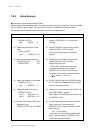
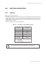
(6) Set the T7ICEDG flag of the TM7MD2 register
to "1" to select the external interrupt valid edge
as a generation source of capture trigger.
(7) Set the timer 7 preset register 1 (TM7PR1) to
x'FFFF'. At that time, the same value is loaded
to the timer 7 compare register 1 (TM7OC1),
and the timer 7 binary counter (TM7BC) is
initialized to x'0000'.
(8) Set the interrupt level by the IRQ0LV1-0 flag of
the IRQ0ICR register. If any interrupt request
flag may be set already, clear them.
(9) Enable the interrupt by setting the IRQ0IE flag
of the IRQ0ICR register to "1".
(10) Enable the capture trigger generation by
setting the T7ICEN flag of the TM7MD2
register to "1".
(11) Set the TM7EN flag of the TM7MD1 register to
"1" to start timer 7.
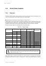
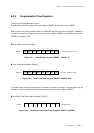
Setup Procedure
(6) Select the capture trigger generation
edge.
TM7MD2 (x'3F79')
bp7 : T7ICEDG = 1
(7) Set the compare register.
TM7PR1(x'3F75',x'3F74') = x'FFFF'
(8) Set the interrupt level.
IRQ0ICR (x'3FE2')
bp7-6 : IRQ0LV1-0= 10
(9) Enable the interrupt.
IRQ0ICR (x'3FE2')
bp1 : IRQ0IE = 1
(10) Enable the capture trigger
generation.
TM7MD2 (x'3F79')
bp2 : T7ICEN = 1
(11) Start the timer operation.
TM7MD1 (x'3F78')
bp4 : TM7EN = 1
Description
[ Chapter 3 3-1-4. Interrupt Flag Setup ]