


4-18
Screens
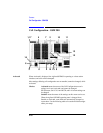
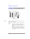
Cell Configuration - GSM 900
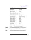
4. Aux BCCH This field allows selection of data and clock outputs.
NOTE This is not featured in the Agilent 8922S.
Choices Off causes the front-panel MODULATION IN/OUT DATA and
CLOCK connectors to be inputs.
Adjacent causes data and clock signals to be output on the front-
panel MODULATION IN/OUT DATA and CLOCK connectors.
These signals can be connected to a 0.3 GMSK generator
(HP/Agilent 8657A/B Option 022.) A mobile station should be
able to camp on to the Aux BCCH.
The BCC (Base Station Colour Code) is displayed in this field and has a number
plus 1 modulo 4 relationship with Serv Cell BCC.
NOTE The data output includes a midamble, which will result in discrete sidebands. If
random data is desired, use an HP/Agilent 8904A Option 001 or 002 to generate
random data and clock signals to the 0.3 GMSK generator.
See Also Connectors and Timing Diagrams: CLOCK (MODULATION)
Connectors and Timing Diagrams: IN/OUT DATA
(MODULATION)
5. BA This field is a 124-element Boolean array defining which ARFCNs are in the base
station allocation. The serving cell ARFCN does not have to be set to a 1 in this
table.
Choices Done exits the choices menu.
Position moves the cursor to the desired position in the array.
0 means the ARFCN is not selected.
1 means the ARFCN is selected.
6. BCC This field sets the base-station color-code portion of the BSIC (base station identity
code) for the serving cell.
Range 0 through 7
7. CA This field is a 124-element Boolean array defining which ARFCNs are in the cell
allocation table. It is used to define the ARFCNs used in the TCH hop sequence.
Choices Done exits the choices menu.
Position moves the cursor to the desired position in the array.
0 means the ARFCN is not selected.
1 means the ARFCN is selected.