


3-8
Verifying Performance
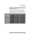
Understanding the Tests
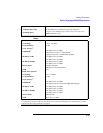
Test 02: Signal
Generator Spectral
Purity
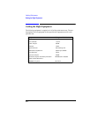
Equipment Required
HP/Agilent 8566B Spectrum Analyzer
Theory of the Test
The UUT is set to generate a CW signal at various levels and frequencies. The HP/
Agilent 8566B is used to measure the signal level and then the level of the
harmonics or spurious signals.
Things To Check In Case Of Problems
• The instruments should have their timebases locked together to assure that the
frequency offsets for the spurious measurements are accurate.
Test 03: Signal Pulse
Modulation
Equipment Required (excluding Agilent 8922M/S)
HP/Agilent 8116APulse Generator
Theory of the Test
The HP/Agilent 8116A pulse generator drives the pulse input of the UUT and
causes it to generate pulsed RF signals. These signals are detected with the negative
diode detector and analyzed with the oscilloscope. The UUT is set to generate two
different on/off ratios: 30 dB and 80 to 90 dB. Rise time and fall time for each of
these is measured.
When the Agilent 8922S is the UUT, the RF Generator is set to generate a pulsed
GMSK signal. This signal is then analyzed with the UUT detector and oscilloscope.
Things To Check In Case Of Problems
• The oscilloscope is used to automatically measure rise and fall times. If the RF
signal has high video feedthrough, it may cause the oscilloscope to make a faulty
reading by triggering on the video feedthrough instead of the actual pulse.
• A diode detector with a greatly different sensitivity may cause the demodulated
waveform to overrange on the oscilloscope or have reduced accuracy because of
the resolution of the oscilloscope.