


2-43
Making Measurements
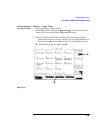
Advanced Features
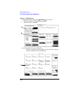
NOTE The GPIB requires the use of base 10 values, 432h = 1074d, for example:
SERV:LATCH:VAL 1074.
The value entered is relative to the beginning of the zero bit of the zero
slot on the downlink baseband.
A 4.7 bit modulator delay occurs between the baseband and the RF
domain which must also be taken into account. Since the value may
only be integer, round to the nearest whole value.
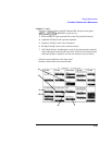
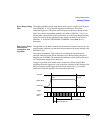
The following timing error is introduced due to 156/157 bit timing.
Timeslot=0,4 No Error
Timeslot=1,5 +.75 bit error (early trigger)
Timeslot=2,6 +.50 bit error
Timeslot=3,7 +.25 bit error
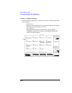
2 Use MEAS_TRIG_OUT on the rear panel SYSTEM_BUS connector.
This is the delayed trigger from the Measurement System. In the normal
ACTIVATED operation, the Protocol Processor sends triggers to the
Measurement System on the zero bit of each downlink TCH burst. The
Measurement System applies the ‘Meas Trig’ ‘Trigger Delay’ to this input and
then, after the elapsed time, begins making its measurement. After this elapsed
time, the Measurement System also sends a trigger transition to the
MEAS_TRIG_OUT signal on the rear panel SYSTEM_BUS connector.
The trigger is only generated when a measurement is being made. This signal
may be used to trigger an externally connected measurement device such as the
HP/Agilent 71150/250 GSM high performance spectrum analyzers.