


4-113
Screens
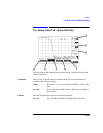
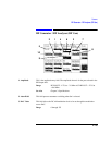
RF Generator / RF Analyzer (RF Analyzer)
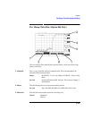
3. Amplitude This field is the input amplitude to be assumed at the selected RF Analyzer input.
The amplitude shown is for the port selected in the RF Input field.
Range RF IN/OUT: −27.9 to +41.0 dBm. AUX RF IN: −58.0 to +20.0
dBm.
See Also Chapter 3: Specifications
4. Control This field determines how the RF Analyzer amplitude is selected.
Choices MS TX Lev automatically selects the RF Analyzer amplitude
based on the level set in TX Level on the Cell Control screen if the
RF analyzer’s RF input connector selection is RF IN/OUT.
Manual requires setting the RF Analyzer amplitude using the
front-panel keys.
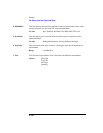
5. Do Open Cal This field is displayed only when AGC Mode is closed. When selected, the correct
Open/Auto DAC Value for the signal input, using the present RF Analyzer setting, is
entered in the Open/Auto Dac Value field.
A stable, repeating RF signal is required for open loop calibration.
Doing an open loop calibration is useful for establishing an AGC DAC Value to be
used when AGC Mode is Open.
See Also Screens: RF Analyzer (AGC Mode, Open/Auto DAC Value)
6. Frequency This field sets Frequency when RF Analyzer Hop Mode is set to Non- Hop.
Range 10.0 to 1015.0 MHz.
7. Hop Meas Freq This is the frequency entry field for the frequency assumed when making
measurements while the RF Analyzer is frequency hopping.
8. Hop Mode This field selects between the Hop and Non-Hop modes of the RF Analyzer. Hop
Mode cannot be set to Non-Hop until Hop Trig is set to Disarm.
NOTE Do not make measurements with Hop Mode set to Hop and Hop Trig set to Disarm.
9. Hop Offset This field sets the Hop Offset when the RF Analyzer Hop Mode is set to Hop. The
frequency offset is applied to all of the frequencies in the RF Analyzer Hop
Frequency table when the RF Analyzer is hopping.
Range −50.000 to +50.000 kHz.