


6-9
Connectors
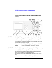
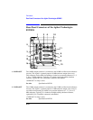
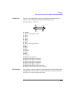
Front-Panel Connectors of the Agilent Technologies 8922M/S
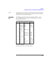
18. TRIGGER IN
(MEASURE)
The measurement trigger input is the trigger source for the oscilloscope, spectrum
analyzer (option 006), Pwr Ramp, Phase/Freq and Data demodulation.
All triggered measurements, when trigger is selected as external, are triggered by
this signal.
It is not possible to separately trigger an oscilloscope or spectrum analyzer
measurement from a Pwr Ramp measurement.
TRIGGER IN is selected when the digital demodulator’s Trig Source is set to Ext
Meas, or when the measurement synchronization Trig Source is set to Ext Meas.
See Also Screens: Phase Freq, Pwr Ramp, Oscilloscope, Spectrum
Analyzer
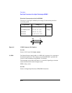
19. VALID
(DEMODULATION
OUT)
(Agilent 8922M
Only)
This connector is connected to the DSP analyzer’s digital demodulation data valid
output.
This signal is the digital demodulation data valid signal which is generated when
digitally demodulating one out of eight timeslots of GSM 0.3 GMSK modulation. It
can be used to load the digitally demodulated data. This signal is used for gate
timing when the demodulation output data-signal and the demodulation output
clock-signal are valid.
This output is only active while outputting, not while demodulating, and it is only
active when the digital demodulation mode is selected and armed.
This connector is connected directly in parallel with DEMOD_VALID on the
SYSTEM BUS connector.
Specifications High drive: 1 mA Low drive: 1 mA Active level: LOW Active
for: leading tailbits, first half of data, midamble, second half of
data, and trailing tailbits. Inactive for: guard bits Duration
depends on type of burst being demodulated.
See Also Screens: Cell Control 2 Specifications Signal Descriptions for
the System Bus