


6-3
Connectors
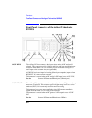
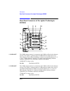
Front-Panel Connectors of the Agilent Technologies 8922M/S
3. CLOCK
(DEMODULATION
OUT)
(Agilent 8922M
Only)
The clock connector is connected to the power ramp’s digital demodulation clock
output. This signal is the digital demodulation CLOCK signal which is generated
when digitally demodulating one out of eight timeslots of GSM 0.3 GMSK
modulation.
CLOCK (DEMODULATION OUT) is only active when the digital demodulation
mode is selected and armed. This is a fast burst of clocks, not a continuous clock.
This connector is undefined when the demodulation output data valid signal is TTL
high
This connector is connected directly in parallel with DEMOD_CLK on the
SYSTEM BUS connector.
Requirements High drive: 1 mA Low drive: 1 mA Duty cycle: 50% Repetition
Rate: 1 MHz
See Also Screens: Pwr Ramp Specifications Signal Descriptions for the
System Bus Timing Diagrams
4. CLOCK
(MODULATION)
(Agilent 8922M
Only)
CLOCK (Input)
The clock connector is connected to the Premod/NSM circuitry. This connector is
used in combination with DATA (MODULATION IN).
CLOCK (MODULATION IN) is selected when the RF generator’s modulation
source GMSK field is set to Ext. This connector is directly in parallel with
FP_CLOCK on the SYSTEM BUS connector.
This must be a continuous signal. Also, significant phase changes or loss of this
signal will result in an out-of-lock condition in the data synchronizer.
NOTE The two inputs are directly coupled to each other. Avoid putting signals on both
inputs simultaneously.
Clock Input Requirements
High drive requirement: 100 µA Low drive requirement: 1.2 mA Active edge: rising
edge