


6-19
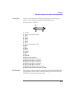
Connectors
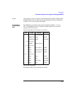
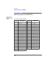
Signal Descriptions for SYSTEM BUS
DEMOD_DATA,
DEMOD_CLK,
DEMOD_VALID
DATA-Pin 22 CLK-Pin 4 VALID-Pin 23 Outputs
These are the digital demodulation data output signal, the digital demodulation
clock output signal, and the digital demodulation valid output signal. These signals
are connected directly in parallel with their respective front-panel connectors.
See Also Front Panel Connectors: DATA (DEMODULATION OUT),
CLOCK (DEMODULATION OUT), VALID
(DEMODULATION OUT)
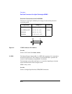
FP_DATA,
FP_CLOCK
DATA-Pin 1 CLOCK-Pin 20 Inputs
These are the front-panel DATA, and CLOCK inputs. These signals are connected
directly in parallel with their respective front-panel connectors.
NOTE The two inputs are directly coupled to each other. Avoid putting signals on both
inputs simultaneously.
See Also DATA (MODULATION IN) CLOCK (MODULATION IN)
G_EXT_TRIG_
OUT
Pin 24 Output
This output is a 1-bit-wide trigger. The timeslot and bit position in the timeslot are
programmable on the Service screen.
Requirements Amplitude: TTL Levels Low Drive: 10 µA High Drive: 2 mA
See Also Screens: Service
MEAS_TRIG_OUT Pin 21 Output
This output signals when a DSP measurement is being made. It is used as an
auxiliary trigger output signal for use with an external spectrum analyzer.