


4-50
Screens
Configure
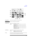
2. Aux RF Out
NOTE This field is only used when the RF Level Offset field is set to On.
This field is used to indicate losses or gains between the AUX RF OUT port and the
device under test.
• Enter a positive value to indicate a gain (such as an amplifier gain). The RF
Generator level is automatically set to that amount below that which is indicated
in the RF Generator’s Amplitude field. (Example; if this value is 10 dB, and
the Amplitude field shows 0 dBm, the actual level out this port is −10 dBm.)
The value at the output of the external amplifier should then be at the level
indicated in the Amplitude field.
• Enter a negative value to indicate a loss (such as cable loss). The RF Generator
level is automatically set above to that amount which is indicated in the RF
Generator’s Amplitude field to compensate. The value at the opposite end of
the cable (loss) should then be at the level indicated in the Amplitude field;
unless the resulting RF Generator setting exceedsthe maximum output level, then
an error occurs - Input value out of range. In that case, increase the
Aux RF Out setting, or increase the Aux RF In power level so that they are
closer to zero.
3. Beeper This field controls the beeper volume.
Choices Off
Quiet
Loud
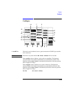
4. Compatible This toggle field allows you to simulate the operation of an Agilent 8922G (from an
Agilent 8922M) or an Agilent 8922E (from an Agilent 8922S). The key
can be used to set the correct Preset conditions after this field has been changed,
although a power cycle is recommended.
5. Date These fields set the date for the internal calendar. The Date can be read by a
controller using GPIB, then printed on test results (YYYY MM DD).
6. Firmware This field displays the firmware revision of the instrument.
7. Intensity This is the CRT intensity adjustment field.
Range 1 to 8.
PRESET