


6-10
Connectors
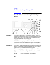
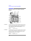
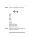
Rear-Panel Connectors of the Agilent Technologies 8922M/S
Rear-Panel Connectors of the Agilent Technologies
8922M/S
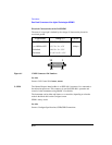
1. 10 MHz OUT The 10 MHz output connector is connected to the 10 MHz oscillator in the reference
circuitry. This signal is a general-purpose 10 MHz reference output (sine wave).
This connector can be either free-running or locked to an external reference of 1, 2,
5, 10 or 13 MHz reference. Typically, it is locked to the high-stability timebase
reference, (option 001) if it is installed, connected, and enabled.
10 MHz OUT is always active.
See Also Specifications REF IN
2. 13 MHz OUT The 13 MHz output connector is connected to the 13 MHz oscillator in the reference
circuitry. This signal is a general-purpose 13 MHz reference output, (sine wave). It
can either be free-running or locked to any external reference of 1, 2, 5, 10 or 13
MHz reference. Typically, it is locked to the high-stability timebase reference,
(option 001) if it is installed, connected, and enabled.
13 MHz OUT is always active.
See Also Specifications REF IN
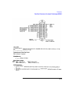
12610
11
8
9
4
13
14
12
7
3
5