6-20
Connectors
Signal Descriptions for SYSTEM BUS
PULSE_MOD_IN Pin 6 Input
This is the pulse modulation input. This signal is connected directly in parallel with
the PULSE (MODULATION IN) front-panel connector.
NOTE The two inputs are directly coupled to each other. Avoid putting signals on both
inputs simultaneously.
See Also Screens: RF Generator Front-Panel Connectors: PULSE
(MODULATION IN)
RP_BURST_T1,
RP_BURST_T2
T1-Pin 26, T2-Pin 8 Select/Control
These are the rear-panel power ramp burst type select signals. They are connected to
the DSP analyzer. These signals can be used during power ramp measurements to
select the burst type in real-time for each burst being operated on.
When digitally demodulating, burst select must be set to Ext to use these signals.
When making triggered measurements, the measurement synchronization burst
selection must be set to Ext. Each of the four burst type definitions can be selected.
Requirements Amplitude: TTL levels High drive requirement: 100 µA Low
drive requirement: 2 mA
See Also Screens: Measurement Sync Specifications Timing Diagrams
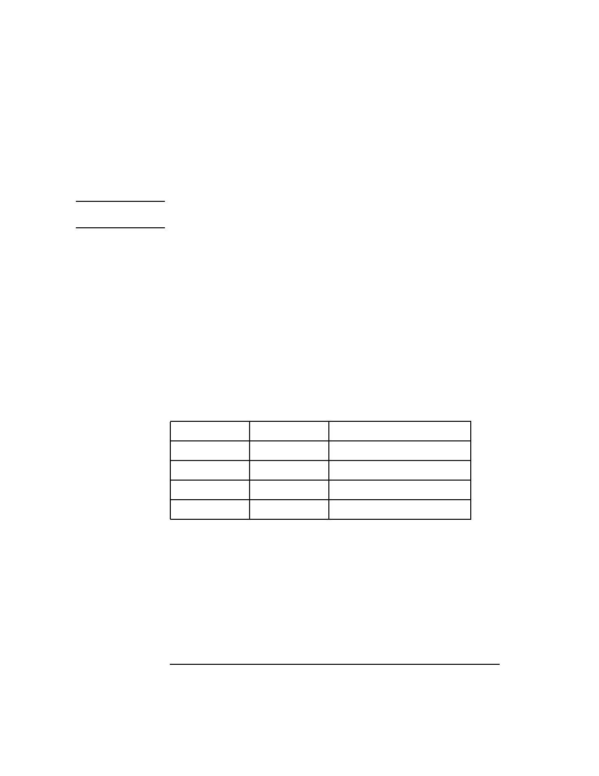
Table 2-2 System Bus Connector Pin Numbers
RP_BURST_T2 RP_BURST_T1 BURST NUMBER SELECTED
TTL LOW TTL LOW 0
TTL LOW TTL HIGH 1
TTL HIGH TTL LOW 2
TTL HIGH TTL HIGH 3


