


4-94
Screens
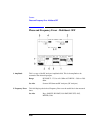
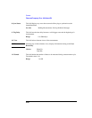
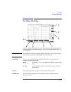
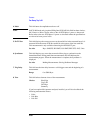
Phase/Freq, Data Bits
NOTE When measuring noisy signals (approx 10° rms), define your entire burst as a User
Defined Sync Pattern, and select Expected. This will eliminate the problem of bit
errors causing gross peak phase errors.
See Also Screens: Measurement Sync
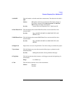
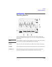
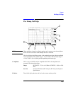
3. Polarity This field toggles the polarity of the displayed bits.
4. SyncStatus This field displays any errors that occurred while trying to synchronize to the
demodulated data.
See Also Making Measurements: Solving Problems Messages
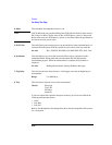
5. Trig Delay This field sets the time delay between a valid trigger event and the beginning of a
measurement.
Range 0 to 5000.00 µs.
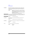
6. Trg Timing This First Bit field displays the position in time of the first useful bit relative to the
delayed measurement trigger.
See Also Keys: ON/OFF, HI LIMIT, LO LIMIT, REF SET, AVG, Units
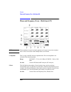
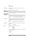
The FMErr Count field displays the number of bit differences
detected when comparing the demodulated data bits to the
selected midamble or user defined synchronization pattern
when Sync Mode is set to Midamble. This field will display 0 if
Sync Mode is set to Amplitude.
Screens: Measurement Sync (Sync Mode)
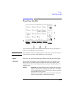
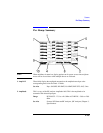
7. View This field selects alternate views of the measurement.
Choices Phase Frq
Phase Err