


6-2
Connectors
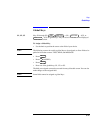
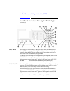
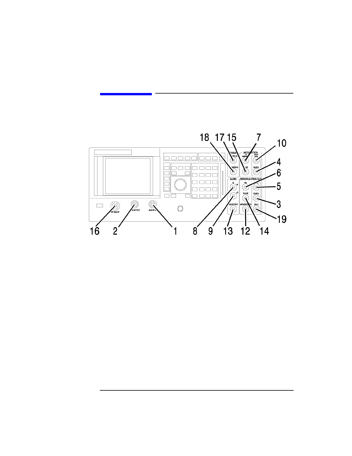
Front-Panel Connectors of the Agilent Technologies 8922M/S
Front-Panel Connectors of the Agilent Technologies
8922M/S
1. AUX RF IN The auxiliary RF input connects to the input section and to the RF analyzer (if
selected). This connector provides a higher sensitivity and lower maximum-power
connection from the DUT. It is not normally used for transceiver testing but is a
useful input to the Spectrum Analyzer (option 006).
AUX RF IN has its own input level setting (RF analyzer amplitude) separate from
RF IN/OUT. It is reverse power protected.
This connector is selected when the RF analyzer’s RF input is set to AUX RF IN.
See Also Screens: RF Generator/RF Analyzer, (RF Analyzer)
2. AUX RF OUT The auxiliary RF output connects to the output section from the RF generator’s step
attenuators (if selected). This connector provides higher output levels to a device-
under-test (DUT). It is not normally used for transceiver testing.
This connector has its own output amplitude setting (RF generator amplitude)
separate from RF IN/OUT. It is reverse power protected.
This connector is selected when the RF generator’s RF output is set to AUX RF
OUT.
See Also Screens: RF Generator/RF Analyzer, (RF Gen)