


6-21
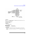
Connectors
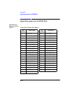
Signal Descriptions for SYSTEM BUS
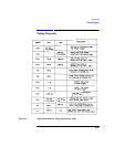
RP_DMOD_TRIG Pin 7 Input
This is the rear-panel trigger signal input for digital demodulation. It connects to the
DSP analyzer. It can also be used for other triggered measurements.
This signal is active when the digital demodulator’s demodulation trigger source is
set to Ext Demod, or when the measurement synchronization trigger source is set to
Ext Demod.
Requirements Amplitude: TTL levels High drive requirements: 100 µA Low
drive requirements: 2 mA Active edge: rising edge.
See Also Screens: Power Ramp, Phase Freq(Data Bits) Specifications
Timing Diagrams
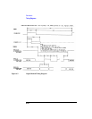
RP_GSM_RST_IN Pin 3 Input
This connector is an active low input that halts and resets the Agilent 8922 GSM
counters (frame, timeslot, and bits). It is used when two or more Agilent 8922M/S
are connected together (daisy-chained) to simulate a GSM system.
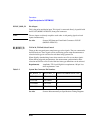
Requirements Amplitude: TTL Levels Low Drive: 100 µA High Drive: 2 mA
Active Level: Low
RP_GSM_RST_
OUT
Pin 5 Output
This connector indicates whether the Agilent 8922M/S GSM counters have been
halted (by RP-GSM-RST-IN). It is always active (TTL Low) when the Agilent
8922M/S is in the Settable Mode.
Requirements Amplitude: TTL Levels Low Drive: 100 µA High Drive: 2 mA
Active Level: Low