


6-4
Connectors
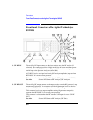
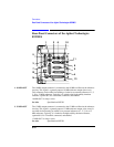
Front-Panel Connectors of the Agilent Technologies 8922M/S
5. DATA
(DEMODULATION
OUT)
(Agilent 8922M
Only)
This connector is the digital demodulation DATA signal which is generated when
digitally demodulating one out of eight timeslots of GSM 0.3 GMSK modulation.
DATA (DEMODULATION OUT) is only active when the demodulation is armed.
This is a fast burst of data, not continuous data.
This output is undefined when the demodulation output data valid signal is TTL
HIGH. Differential data decoding is done internally.
DATA (DEMODULATION OUT) is active only when the digital demodulator’s
State field is set to Arm.
This connector is connected directly in parallel with DEMOD_DATA on the
SYSTEM BUS connector.
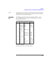
Requirements High drive: 1 mA Low drive: 1 mA
See Also Screens: Cell Control 2 Specifications Signal Descriptions for
the System Bus Timing Diagrams
6. FM
(DEMODULATION
OUT)
(Agilent 8922M
Only)
The FM connector is connected to the receiver circuitry. This connector provides an
output of the FM discriminated signal.
This signal is muted whenever the pulsed RF input signal is OFF.
This output is always active.
See Also Specifications
7. IN AM/SPEECH
(MODULATION)
(Agilent 8922M
Only)
This connector can be used for transmitting speech to a mobile phone. To select
speech, choose Cond or Uncond from the Cell Control 2 screen, Speech field.
This connector is also used as the DC AM input of the Agilent 8922M/S. To select
DC AM, choose Ext from the RF Generator/RF Analyzer screen, DC AM field. The
RF carrier will now be AM modulated (with fixed sensitivity) through this
connector.
See Also Screens: Cell Control 2 (Speech) Screens: RF Generator/RF
Analyzer, (RF Gen) (DC AM) Screens: Audio, (AF Anl In)
Specifications
NOTE IN AM/SPEECH and AM IN (a rear-panel connector) are connected directly in
parallel. Avoid putting signals on both inputs simultaneously.