


2-17
Making Measurements
Measurements
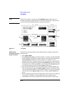
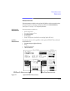
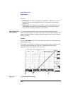
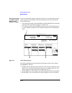
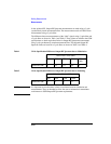
The power ramp measurements are divided into three screens where you can view
different parts of the signal and one screen which displays a series of amplitude
values at various times during the burst. These screens can be revealed by
highlighting and selecting from the View field (2):
• Rise Edge - displays the top 30 dB of the rising section of the waveform.
• Top 2 dB - displays the signal during the middle part of the burst allowing
analysis of the ripple of the signal.
• Fall Edge - displays the signal during the falling edge of the burst allowing
analysis of the fall time of the signal.
• Summary - details the amplitude measurements made at the times selected in the
12 time fields. You can choose your own time-positions, or use the default
settings.
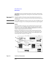
The sensitivity of the Agilent 8922M/S receiver can be varied (3) allowing you to
verify whether the input signal level matches the Agilent 8922M/S RF Analyzer.
Valid measurements are only made when the signal is within 3 dB of the RF
Analyzer setting.
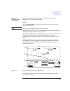
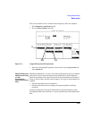
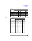
Measurement
Summary
The Measurement Summary field on the DSP Analyzer Ampl Main screen displays
whether HI/LO limits set for the measurement display fields, (Ampl1-12, pk+
flatness, or pk- flatness) were exceeded in the last measurement. The possible
Measurement Summary displays are:
Failed
One or more measurement limit was exceeded.
Passed
No measurement limits were exceeded.
- - - -
No measurement limits are set, or, all of the Ampl and Pk measurement displays are
turned off.
A blank field
The blank field is displayed when the measurement is armed. It will remain blank
until the measurement is complete.
Refer to “Pulse Measurements” within this section for a description of Pulse
Measurements. These measurements are available with option 006 only.