2-10
Making Measurements
TEST MODE
NOTE While the Test Mode is selected, the three MEASURE ON parameters are also
available on the bottom right-hand side of all measurement screens. This provides
control of the Expected Input parameters during measurements.
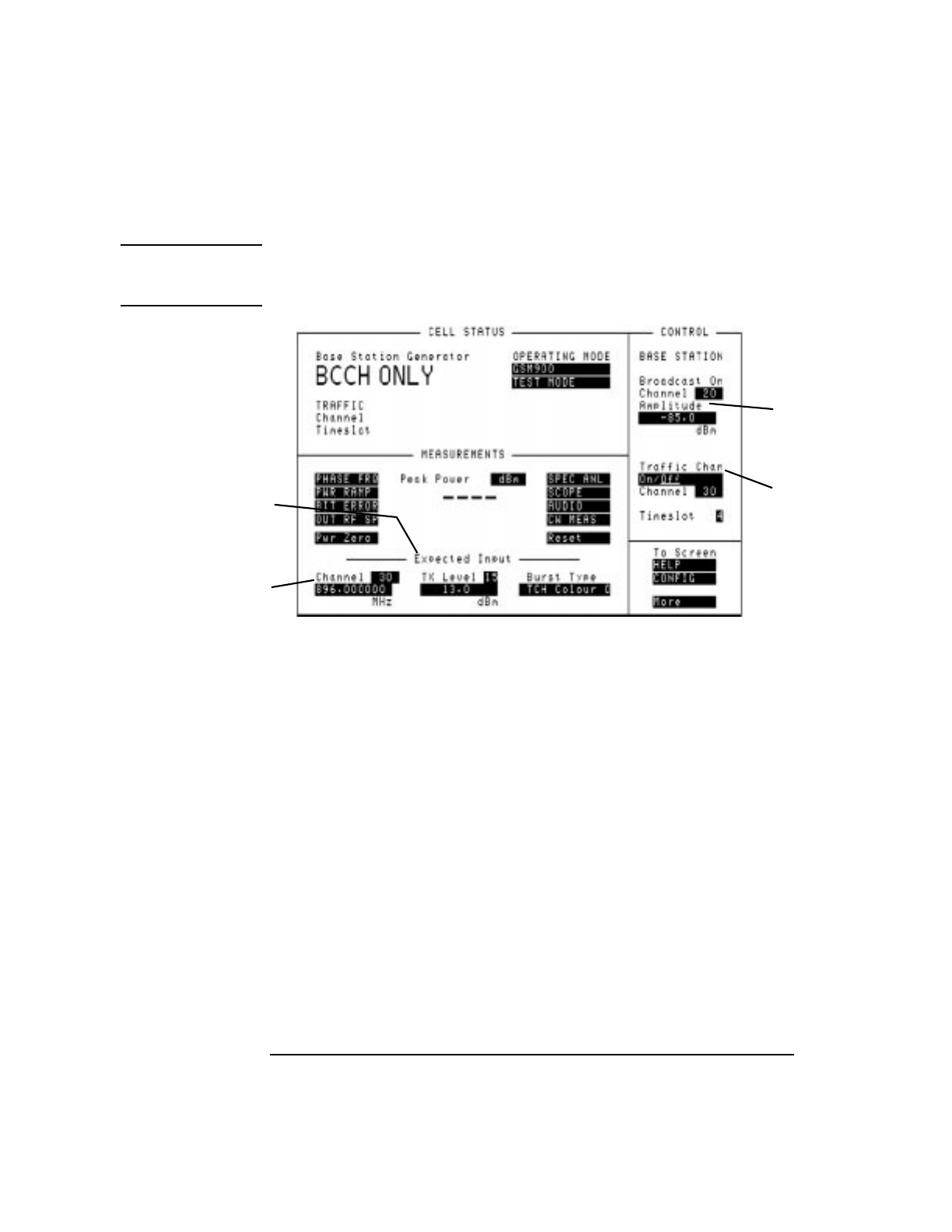
Figure 2-3 Test Mode
Mobile Phone
Transmitter Testing
Using Test Mode
To measure an incoming signal from the mobile phone’s transmitter, perform the
following steps:
• Select TEST MODE.
• In the Expected Input area, (2), see Figure 2-3 on page 2-10, enter the GSM
channel number of the signal to be measured. This will automatically update the
input Frequency field below it, (3), see Figure 2-3 on page 2-10. If a
frequency needs to be measured which does not correspond to a standard GSM
channel, enter the non-standard value into the Frequency field. This value can
be anywhere from 10 MHz to 1000 MHz. A direct entry in the Frequency field
over-rides the frequency defined by the Channel field above.
• Enter the expected transmit level of the mobile phone in the TX Level field.
This will automatically update the Amplitude field below with the equivalent
TX level represented in dBm. If a non-standard input level is expected, enter the
value directly into the Amplitude field, this overrides the TX Level field
above.
• Enter the expected Colour Codeof the input signal. The Colour Codeis a function
of the central “midamble” of the transmitted burst and is needed so that
measurements are correctly synchronized to the received burst. If the Colour
3
2
1
4
