


6-8
Connectors
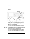
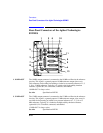
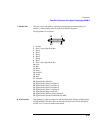
Front-Panel Connectors of the Agilent Technologies 8922M/S
15. PULSE
(MODULATION)
(Agilent 8922M
Only)
The PULSE connector connects to the hop controller and to the RF output section
(when selected as active).
This signal is the TTL input to externally control when the amplitude is pulsed ON
(TTL HIGH) or OFF (TTL LOW). It also pulses the envelope up (TTL HIGH) and
down (TTL LOW) when in 30 dB Pulse mode.
This connector can be used in combination with AM (MODULATION IN) to
generate pulsed and/or shaped amplitude envelopes of different levels for each RF
generator pulse in real-time.
PULSE (MODULATION IN) is selected when the RF generator’s modulation
source Pulse field is set to Ext. This connector is connected directly in parallel with
PULSE_MOD_IN on the SYSTEM BUS connector.
NOTE The two inputs are directly coupled to each other. Avoid putting signals on both
inputs simultaneously.
Requirements High drive requirements: 100 µA Low drive requirements: 1
mA TTL HIGH: On or Higher Level TTL LOW: Off or Lower
Level
See Also Screens: RF Generator/RF Analyzer (Mod Source)
Specifications Signal Descriptions for the System Bus
16. RF IN/OUT The RF input/output is connected to the input section to the RF analyzer and the RF
generator’s step attenuators. It is the main device-under-test (DUT) connection for
the radio’s RF signals. It is normally used for transceiver testing. This connector is
not reverse power protected, but can handle high power levels for extended periods
of time because there is a temperature sensor for this signal.
WARNING: If you have the Agilent 8922M/S Option 010 Multi-Band Test System, do not
connect the mobile to this port.
This is connector is selected when the RF generator’s RF output is set to RF IN/
OUT or when the RF analyzer’s RF input is set to RF IN/OUT.
17. SCOPE IN
(MEASURE)
The measurement input for the oscilloscope connects to the Audio analyzer and to
the oscilloscope (when selected as an Audio analyzer input source). This is the input
for general purpose oscilloscope measurements, but it can be used for other
measurements as well (for example, audio analyzer measurements, filtering an audio
signal when used with the demodulation output monitor signal).
See Also Screens: Oscilloscope