


4-65
Screens
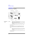
Measurement Sync
4. Burst Sel This field selects the burst that the measurement will synchronize to.
Choices 0
1
2
3
Ext is used for selecting burst number 0, 1, 2, or 3 in real- time
using the SYSTEM BUS (rear-panel connector) or using internal
signals while Activated.
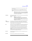
5. Burst Type This field defines the burst type. Choose from eleven burst types, or User Def for
specifying a user defined burst type.
Choices TSC0 through TSC7 (Training Sequence Codes) are used for
normal bursts.
RACH (Random Access Channel) is used for access bursts.
SCH (Synchronization Channel) is used for synchronization
bursts.
FCH (Frequency Channel) is used for frequency correction bursts.
User Def (User Defined) is used when your burst does not conform
to any of the burst types listed (such as PRBS), or when measuring
noisy signals.
User defined burst lengths must be 87 or 147 (plus 4 guard bits), and the User
Defined Sync Pattern can comprise part of or all of the bits in the burst.
To measure a noisy signal (approx 10 deg rms), enter the entire burst in User
Defined Sync Pattern, and use Midamble Expected (see Screens: DSP Analyzer:
Data Bits or Phase Err). The ideal phase trajectory will be calculated from the User
Defined Sync Pattern, eliminating the problem of extremely high peak phase error
due to bit errors.
User Def is not allowed for Digital Demod.
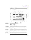
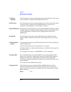
6. Burst Type This field displays a summary of the Burst Type definitions for the four definable
bursts.
7. Burst Used This field displays which one of four possible burst types was used for
synchronization or alignment during a measurement. Refer to the Burst Definition
or Burst Def fields.