


2-16
Making Measurements
Measurements
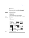
These are:
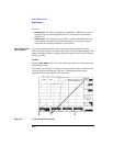
• PHASE ERR - this displays the phase error graphically. The phase error trace is
displayed using an autoscaling phase error axis versus data bits (numbered 0
through 147).
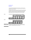
• DATA BITS - this screen allows you display a screen which details the values
of the 148 bits in the timeslot (including midamble). If a known test signal is
being used, the reception of these bits can be verified.
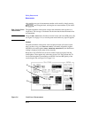
Power Ramp Mask
Measurements
To avoid unwanted interference and to ensure successful reception at the Base
Station, the mobile phone’s transmitted signal must conform to GSM standards. The
purpose of the power ramp is to display the pulsed signal and verify that it conforms
to these standards.
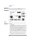
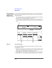
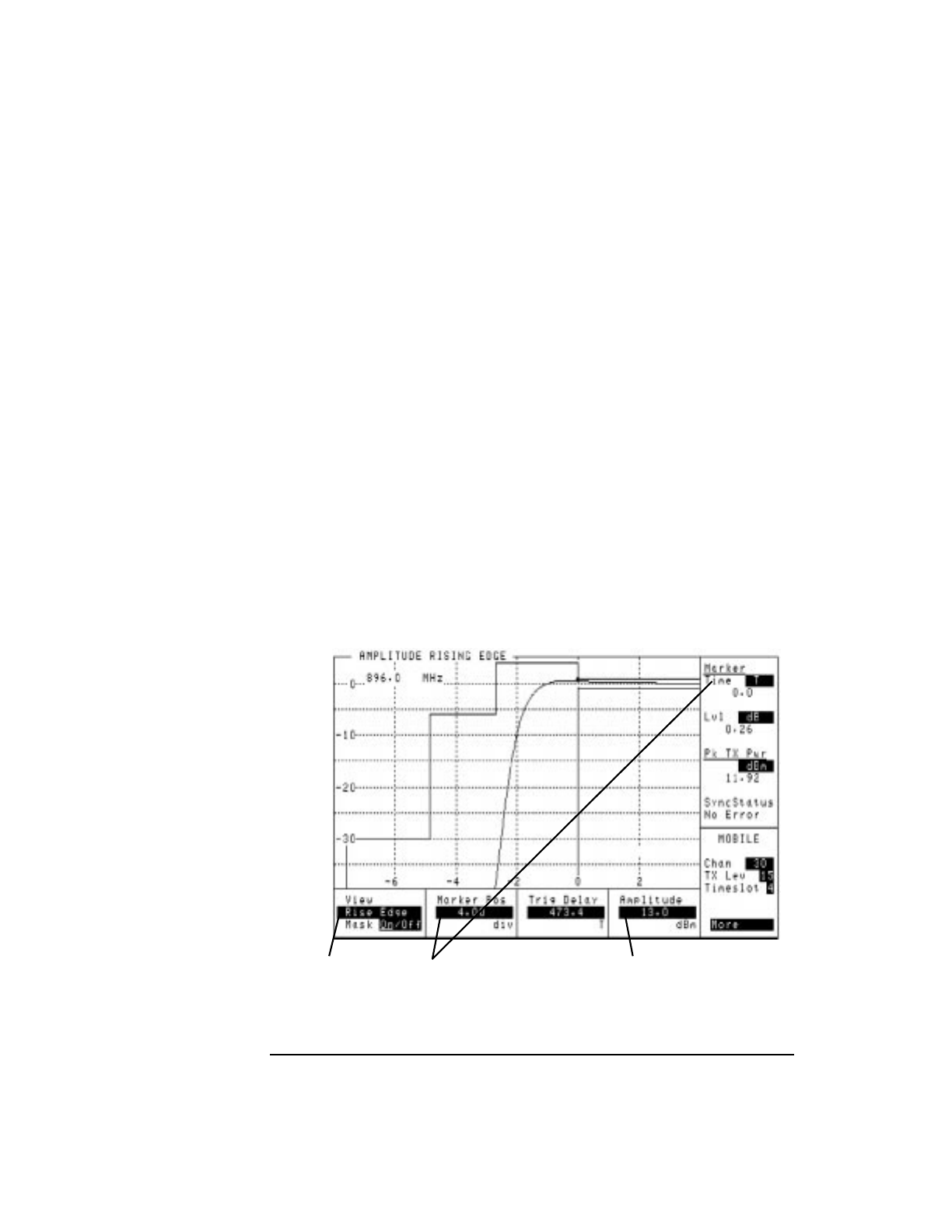
Method
Selecting PWR RAMP on the cell control screen gives you access to the power ramp
measurement screens.
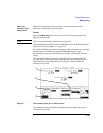
The marker (1), see Figure 2-8 on page 2-16 can be used to make a measurement at
a discrete point in time along the signal trace. The amplitude at this point is
displayed in the top left-hand corner of the screen.
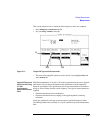
Figure 2-8 Power Ramp Measurements
2
1
3