


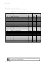
Chapter 3 Interrupts
III - 10
Overview
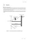
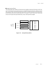
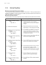
■Interrupt Acceptance Operation
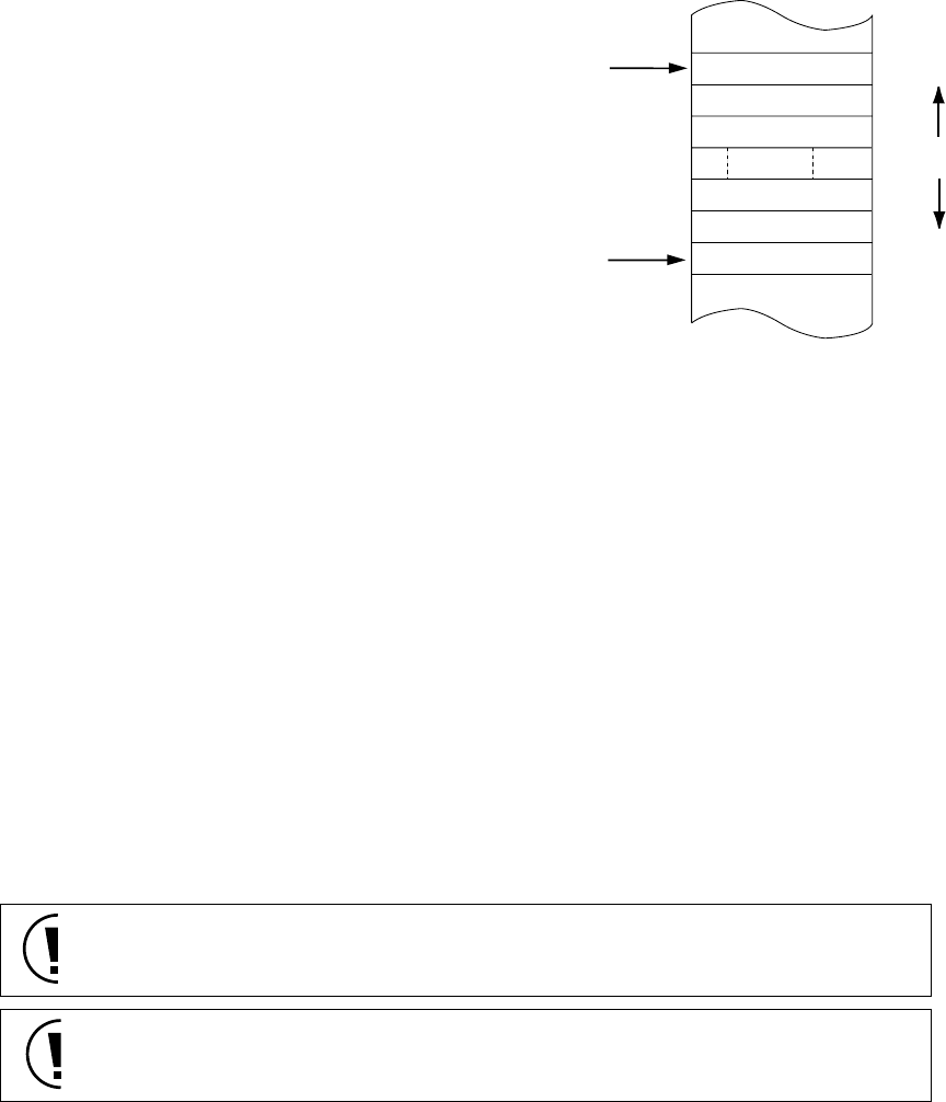
When accepting an interrupt, this LSI hardware saves the handy address register, the return address
from the program counter, and the processor status word (PSW) to the stack and branches to the
interrupt handler using the starting address in the vector table.
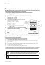
The following is the hardware processing sequence after by interrupt acceptance.
1. The stack pointer (SP) is updated.
(SP-6 → SP)
2. The contents of the handy address register (HA) are saved to the stack.
Upper half of HA → (SP+5)
Lower half of HA → (SP+4)
3. The contents of the program counter (PC), the return
address, are saved to the stack.
PC bits 18, 17, and 0 → (SP+3)
PC bits 16-9 → (SP+2)
PC bits 8-1 → (SP+1)
4. The contents of the PSW are saved to the stack.
PSW → (SP)
5. The interrupt level (xxxLVn) for the interrupt is copied to
the interrupt mask (IMn) in the PSW.
Interrupt level (xxxLVn) → IMn
6. The hardware branches to the address in the vector
table.
■Interrupt Return Operation
An interrupt handler ends by restoring, using the POP instruction and other means, the contents of any
registers used during processing and then executing the return from interrupt (RTI) instruction to return
to the point at which execution was interrupted.
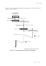
The following is the processing sequence after the RTI instruction.
1. The contents of the PSW are restored from the stack. (SP)
2. The contents of the program counter (PC), the return address, are restored from the stack.
(SP+1 to SP+3)
3. The contents of the handy address register (HA) are restored from the stack. (SP+4, SP+5)
4. The stack pointer is updated. (SP+6 → SP)
5. Execution branches to the address in the program counter.
The handy address register is an internal register used by the handy addressing function. The hardware
saves its contents to the stack to prevent the interrupt from interfering with operation of the function.
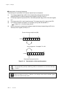
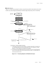
PSW
New SP
(after interrupt
acceptance)
7
0
PC8 - 1
PC16 - 9
PC 18,17
HA 7 - 0
HA 15 - 8
PC0
Old SP
(before interrupt
acceptance)
Lower
Address
Higher
Reserved
Figure 3-1-5 Stack Operation
during interrupt acceptance
Registers such as data register, or address register are not saved, so that PUSH instruction
should be used to save data register or address register onto the stack, if neccessary.
The address bp6 to bp2, when program counter (PC) are saved to the stack, are reserved.
Do not change by program.