


Chapter 6 8-bit Timers
VI - 2
Overview
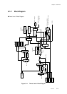
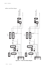
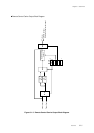
6-1 Overview
This LSI contains two general purpose 8-bit timers (Timers 0 and 1) and two 8-bit timers (Timers 4 and 5)
that can be also used as baud rate timer. The general purpose 8-bit timers can be used as 16-bit timers with
cascade connection.
Fosc or fs can be selected as the clock source for each timer by using the prescaler. Also, remote control
output circuit is built in.
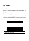
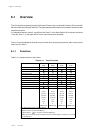
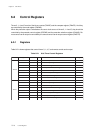
6-1-1 Functions
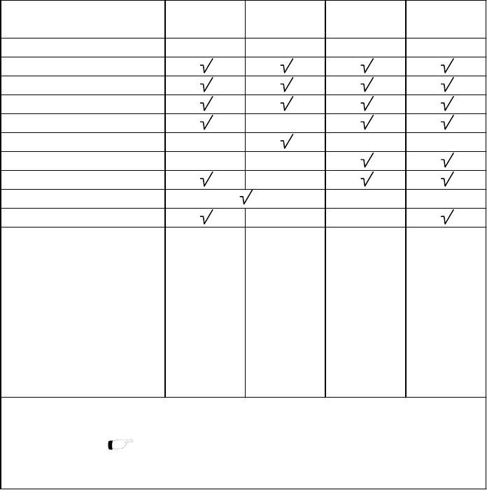
Table 6-1-1 shows functions of each timer.
Table 6-1-1 Timer Functions
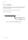
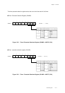
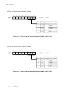
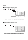
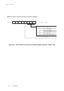
In a cascade connecion, timers 0, 4 and 5 form the "timer 0", or the lower 8 bits of 16-bit counter, and timers
1 form the "timer 1", or the upper 8 bits. Timers 4 and 5 cannot be cascaded.
Timer 0Timer 1Timer 4Timer 5
(8 bit) (8 bit) (8 bit) (8 bit)
Interrupt source TM0IRQ TM1IRQ TM4IRQ TM5IRQ
Timer operation
Event count
Timer pulse output
PWM output -
Synchronous output - - -
Serial transfer clock output - -
Pulse width measurement -
Cascade connection - -
Premote control carrier output - -
Clock source fosc fosc fosc fosc
fosc/4 fosc/4 fosc/4 fosc/4
fosc/16 fosc/16 fosc/16 fosc/16
fosc/32 fosc/64 fosc/32 fosc/32
fosc/64 fosc/128 fosc/64 fosc/64
fs/2 fs/2 fs/2 fs/2
fs/4 fs/8 fs/4 fs/4
fx fx fx fx
TM0IO input TM1IO input TM4IO input TM5IO input
-When timer 4 and 5 are used as a transfer clock for serial interface 1 function, it is not used
as a general timer.
fosc: Machine clock (High speed oscillation)
fx: Machine clock (Low speed oscillation)
fs: System clock [ Chapter 2 2.5 Clock Switching]