


VII - 17
Chapter 7 16-bit Timer
16-bit Event Count
7-4-2 Setup Example
Event Count Setup Example (Timer 7)
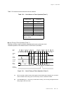
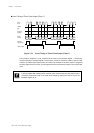
If the falling edge of the TM7IO input pin signal is detected 5 times with using timer 7, an interrupt is
generated. An example setup procedure, with a description of each step is shown below.
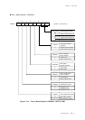
(1) Set the TM7EN flag of the timer 7 mode register
1 (TM7MD1) to "0" to stop timer 7 counting.
(2) Set the P1DIR4 flag of the port 1 direction
control register (P1DIR) to "0" to set P14 pin to
input mode.
If it needs, pull-up resistor should be added.
(3) Set the TM7BCR flag of the timer 7 mode
register 2 (TM7MD2) to "1" to select the
compare match as a clear source of binary
counter.
(4) Select the TM7IO input as a clock source by the
TM7CK1-0 flag of the TM7MD1 register. Also,
select 1/1(no division) as a count clock source
by the TM7PS1-0 flag.
(5) Set the interrupt generation cycle to the timer 7
preset register 1 (TM7PR1). The set value
should be 4, because the counting is 5 times.
At that time, the same value is loaded to the
timer 7 compare register 1 (TM7OC1), and the
timer 7 binary counter (TM7BC) is initialized to
x'0000'.
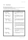
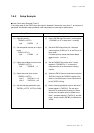
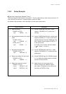
Setup Procedure
(1) Stop the counter.
TM7MD1 (x'3F78')
bp4 : TM7EN = 0
(2) Set the special function pin to input
mode.
P1DIR (x'3F31')
bp4 : P1DIR4 = 0
(3) Select the condition for timer clear.
TM7MD2 (x'3F79')
bp5 : TM7BCR = 1
(4) Select the count clock source.
TM7MD1 (x'3F78')
bp1-0 : TM7CK1-0 = 10
bp3-2 : TM7PS1-0 = 00
(5) Set the interrupt generation cycle.
TM7PR1 (x'3F75', x'3F74')=x'0004'
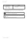
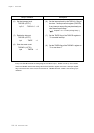
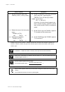
Description
[ Chapter 4 I/O Ports ]