


IV - 17
Chapter 4 I/O Ports
Port 2
4-4 Port 2
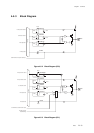
4-4-1 Description
General Port Setup
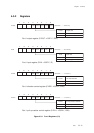
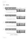
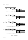
Each bit of the port 2 control I/O direction register (P2DIR) can be set individually to set pins as input or
output. The control flag of the port 2 direction control register (P2DIR) should be set to "1" for output
mode, and "0" for input mode.
To read input data of pin, set the control flag of the port 2 direction control register (P2DIR) to "0" and
read the value of the port 2 input register (P2IN).
To output data to pin, set the control flag of the port 2 direction control register (P2DIR) to "1" and write
the value of the port 2 output register (P2OUT).
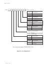
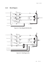
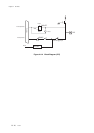
P27 is reset pin. When the software is reset, write the bp7 of the port 2 output register (P2OUT) to "0".
Except P27, each bit can be set individually whether pull-up resistor is added or not, byt the port 2 pull-up
resistor control register (P2PLU). When the control flag of the port 2 pull-up resistor control register
(P2PLU) is set to "1", pull-up resistor is added. P27 is always added pull-up resistor.
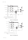
Special Function Pin Setup
P20 to P24 are used as external interrupt pins, as well.
P21 is used as an input pin for external interrupt and AC zero-cross. To read data of AC zero-cross, set the
bp7 of the noise filter control register (NFCTR0) to "1" and read the value of the port 2 input register (P2IN).