


Chapter 7 16-bit Timer
VII - 22
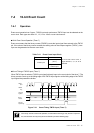
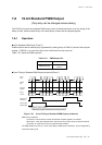
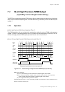
16-bit Timer Pulse Output
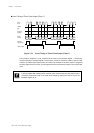
At TM7OC1 = x'0000' and x'0001', the timer pulse output has the same waveform.
Either binary counter stops or operates, the timer output is "L", when the TM7CL flag of the
TM7MD2 register is set to "1".
TM7BC counts up from x'0000'. If TM7BC reaches the set value of the TM7OC1 register and
TM7BC is cleared to x'0000', the signal of the TM7IO output is inverted and TM7BC counts up from
x'0000', again.
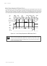
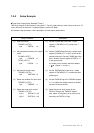
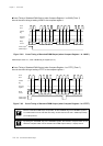
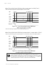
(6) Set the 1/2 frequency of the timer pulse output
cycle to the timer 7 preset register 1
(TM7PR1). To be 100 kHz by a divided
20 MHz, set as follows ;
200 - 1 = 199 (x'C7')
At that time, the same value is loaded to the
timer 7 compare register 1 (TM7OC1) and the
timer 7 binary counter (TM7BC) is initialized to
x'0000'.
(7) Set the TN7CL flag of the TM7MD 1 register to
"0" to enable the timer pulse output.
(8) Set the TM7EN flag of the TM7MD1 register to
"1" to start timer 7.
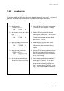
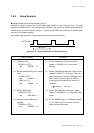
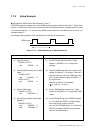
Setup Procedure
(6) Set the timer pulse output cycle.
TM7PR1 (X'3F75', X'3F74')=x'00C7'
(7) Release the reset of the timer pulse
output.
TM7MD1 (x'3F78')
bp5 : TM7CL = 0
(8) Start the timer operation.
TM7MD1 (x'3F78')
bp4 : TM7EN = 1
Description
Set the compare register value as follows.
The compare register value = - 1
The timer pulse output cycle
The count clock cycle x 2
Write to preset register should be done while timer is stopped or within timer interrupt pro-
cessing.
And use MOVW instruction for write to preset register.