


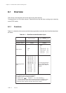
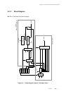
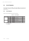

Chapter 7 16-bit Timer
VII - 36
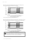
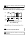
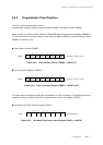
16-bit Timer Capture
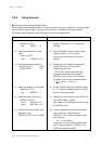
Capture Operation that the writing to program is selected as a Trigger (Timer 7)
A capture trigger can be generated by writing an arbitrary value to the input capture register (TM7IC),
and at the same timing, the value of the binary counter can be stored to the input capture register.
N
0113 0114 5555
5556
Count
clock
TMnEN
flag
Compare
register
Binary
counter
Capture
register
5557 5558 N-1
N
0000 0001 0111
0112
N
0114
0000
Capture trigger
(Synchronous to
writing signal)
5558
System
clock
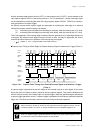
A capture trigger is generated at the writing signal to the input capture register. The writing signal is
generated at the last cycle of the writing instruction. At this timing, the value of the binary counter is
stored to the input capture register. That value is decided by the value of the binary counter at the
falling edge of the capture trigger. The other timing is same to the timer operation.
Figure 7-9-2 Capture Count Timing
with a Writing Signal to Program as a Trigger (Timer 7)
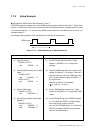
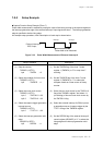
In the initial state after releasing the reset, the generation of trigger by the external interrupt
signal is disabled. Set the T7ICEN flag of the TM7MD2 register to "1" to enable the trigger
generation.
On hardware, there is no flag to disable the capture operation with the writing operation to the
software as a trigger. Capture operation is enabled, regardless of the T7ICEN flag of the
TM7MD2 register.
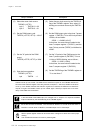
The writing to the input capture register to generate a capture trigger should be done with a 8-
bit access instruction to the TM7ICL register or the TM7ICH register.
At this time, data is not actually written to the TM7IC register.