


Chapter 11 Serial Interface 0, 1
XI - 60
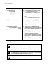
Operation
Note : (6) to (7), (8) to (10), (11) to (13) can be set at once.
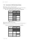
(14) Set the SC0RIE flag of the SC0RICR register
to "1", and set the SC0TIE flag ot the
SC0TICR register to "1" to enable the interrupt
request.
If any interrupt request flag is already set, clear
them.
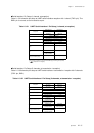
(15) Set the baud rate timer by the TM5MD register,
the TM5OC register. Set the TM5EN flag to "1" to
start timer 4.
(16) The transmission is started by setting the
transmission data to the serial transmission data
buffer (TXBUF0). When the transmission has
finished, the serial 0 transmission interrupt
(SC0TIRQ) is generated. After the serial data is
input from the RXD0A pin and the start condition is
recognized, the received data is stored.
When the reception has finished, the received
data is stored to the serial received data buffer
RXBUF0 and the serial 0 reception data buffer
interrupt SC0RICR is generated.
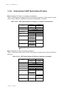
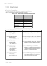
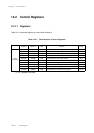
Setup Procedure Description
(14) Enable the interrupt.
SC0RICR (x'3FF4')
bp1 : SC0RIE = 1
SC0TICR (x'3FF5')
bp1 : SC0TIE = 1
(15) Set the baud rate timer.
(16) Start serial communication.
The transmission data → TXBUF0
(x'3F91')
The received data → input to RXD0A
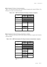
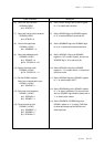
When the TXD0 / RXD0 pin are connected for communication with 1 channel, the TXD0 pin
inputs / outputs serial data. The port direction control register P0DIR switches I/O. At recep-
tion, set SC0SBIOS of the SC0MD1 register to "1" to select serial data input. The RXD0 pin
can be used as a general port.
It is possible to shut down the communication. If the communication should be stopped by
force, set SC0SBOS and SC0SBIS of the SC0MD1 register to "0".
Each flag should be set as its procedure in order. Activation for communication should be
operated after all control registers (except Table 11-2-1 : TXBUF0, RXBUF0) are set.
[ Chapter 6. 6-8 Serial Transfer Clock ]
[ Chapter 3. 3-1-4 Interrupt Flag Setup ]