


Chapter 1 Overview
I - 12
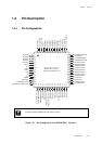
Pin Description
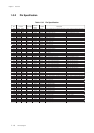
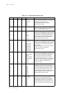
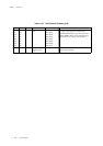
Table 1-3-4 Pin Function Summary (2/6)
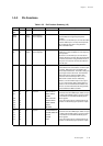
Name No. I/O Function Other Function Description
P20 27 I/O I/O port 2 IRQ0
P21 28 IRQ1, ACZ
P22 29 IRQ2
P23 30 IRQ3
P24 31 IRQ4
P27 14 Input I/O port 2 NRST P27 has an n-channel open-drain configuration.
When "0" is written and the reset is initiated by
software, a low level will be output.
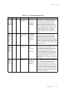
P50 32 I/O I/O port 5 SBI3
P51 33 SBO3,
P52 34 SBT3
P53 35 SDA4A
P54 36 SCL4A
P60 37 I/O I/O port 6 SDO0, KEY0
P61 38 SDO1, KEY1
P62 39 SDO2, KEY2
P63 40 SDO3, KEY3
P64 41 SDO4, KEY4
P65 42 SDO5, KEY5
P66 43 SDO6, KEY6
P67 44 SDO7, KEY7
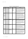
P70 45 I/O I/O port 7 SBO0B, TXD0B
P71 46 SBI0B, RXD0B
P72 47 SBT0B
P73 48 SBO1B, TXD1B
P74 49 SBI1B, RXD1B
P75 50 SBT1B
P76 51 TCI01
P77 52 TCI05
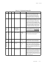
P80 60 I/O I/O port 8 LED0
P81 59 LED1
P82 58 LED2
P83 57 LED3
P84 56 LED4
P85 55 LED5
P86 54 LED6
P87 53 LED7
PA0 62 I/O I/O port A AN0, DA0
PA1 63 AN1, DA1
PA2 64 AN2
PA3 1 AN3
PA4 2 AN4
PA5 3 AN5
PA6 4 AN6
8-Bit CMOS tri-state I/O port. Each bit can be set
individually as either an input or output by the
P8DIR register. A pull-up resistor for each bit can
be selected individually by the P8PLU register.
When configured as outputs, these pins can
drive LEDs directly. At reset, the P80to P87 input
mode is selected and pull- up resistors are
disabled. (high impedance output)
6-Bit I/O port. A pull-up or pull-down resistor for
each bit can be selected individually by the
PAPLUD resister. However, pull-up and pull-
down resistors cannot be mixed. At reset, the
PA0 to PA6 input mode is selected and pull- up
resistors are disabled. (high impedance output)
5-Bit CMOS tri-state I/O port.
A pull-up resistor for each bit can be selected
individually by the P2PLU register.
At reset, pull-up resistors are disabled
(high impedance output).
5-Bit CMOS tri-state I/O port.
Each bit can be set individually as either an input
or output by the P5DIR register. A pull-up resistor
for each bit can be selected individually by the
P5PLU register. At reset, the P50t o P54 input
mode is selected and pull- up resistors are
disabled. (high impedance output)
8-Bit CMOS tri-state I/O port.
Each bit can be set individually as either an input
or output by the P6DIR register. A pull-up resistor
for each bit can be selected individually by the
P6PLU register.
At reset, the P60 to P67 input mode is selected
and pull- up resistors are disabled.
(high impedance output)
8-Bit CMOS tri-state I/O port.
Each bit can be set individually as either an input
or output by the P7DIR register. A pull-up/pull-
down resistor for each bit can be selected
individually by the P7PLU register. However,
pull-up and pull-down resistors cannot be mixed.
At reset, the P70to P77 input mode is selected
and pull- up resistors are disabled. (high
impedance output)