


Chapter 6 8-bit Timers
VI - 28
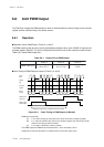
8-bit PWM Output
6-6-2 Setup Example
PWM Output Setup Example (Timers 0, 4 and 5)
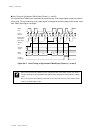
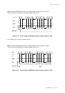
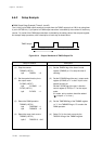
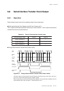
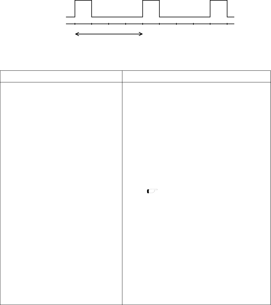
The 1/4 duty cycle PWM output waveform is output from the TM0IO output pin at 128 Hz by using timer
0 (at fx=32.768 kHz). Cycle period of PWM output waveform is decided by the overflow of the binary
counter. "H" period of the PWM output waveform is decided by the setting value of the compare register.
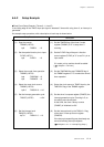
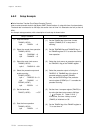
An example setup procedure, with a description of each step is shown below.
TM0IO output
128 Hz
Figure 6-6-4 Output Waveform of TM0IO Output Pin
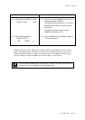
(1) Set the TM0EN flag of the timer 0 mode
register (TM0MD) to "0" to stop the timer 0
counting.
(2) Set the P1OMD0 flag of the port 1 output mode
register (P1OMD) to "1" to set P10 pin to the
special function pin.
Set the P1DIR0 flag of the port 1 direction
control register (P1DIR) to "1" for the output
mode.
If it needs, pull up resistor should be added.
(3) Set the TM0PWM flag of the TM0MD register
to "1", the TM0MOD flag to "0" to select the
PWM operation.
(4) Select "fx" for the clock source by the
TM0CK2-0 flag of the TM0MD register.
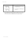
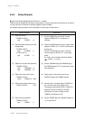
Setup Procedure
(1) Stop the counter.
TM0MD (x'3F54')
bp3 :TM0EN = 0
(2) Set the special function pin to
the output mode.
P1OMD (x'3F2F')
bp0 :P1OMD0 = 1
P1DIR (x'3F31')
bp0 :P1DIR0 = 1
(3) Select the PWM operation.
TM0MD (x'3F54')
bp4 :TM0PWM = 1
bp5 :TM0MOD = 0
(4) Select the count clock source.
TM0MD (x'3F54')
bp2-0 :TM0CK2-0 = 010
Description
[ Chapter 4. I/O Ports ]