


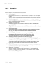


Operation
Chapter 15 A/D Converter
XV - 15
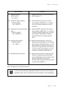
(7) Enable the interrupt by setting the ADIE flag of
the ADICR register to "1".
(8) Set the ANLADE flag of the A/D converter
control register 0 (ANCTR0) to "1" to send a
current to the ladder resistance for the A/D
conversion.
(9) Set the ANSTSEL flag of the A/D converter
control register 2 (ANCTR2) to "1", and select
"writing to the ANST flag of the A/D converter
control register 3 (ANCTR3), the external
interrupt 3"as the A/D converter activation
factor.
(10) When the external interrupt 3, set in (5) is
generated, the ANST flag of the A/D converter
control register 2 (ANCTR2) is set to "1" to start
the A/D conversion. And even if the external
interrupt 3 is not generated, the A/D conversion
is started by setting the ANST flag of the A/D
converter control register 2 (ANCTR2) to "1".
(11) When the A/D conversion is finished, the A/D
conversion complete interrupt is generated,
and the ANST flag of the A/D converter control
register 2 (ANCTR2) is cleared to "0".
The result of the conversion is stored to the A/D
converter buffer (ANBUF0, 1).
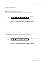
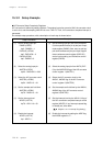
Setup Procedure
(7) Enable the interrupt.
ADICR (x'3FFA')
bp1 : ADIE = 1
(8) Set the A/D ladder resistance.
ANCTR0 (x'3FB0')
bp3 : ANLADE = 1
(9) Select the A/D converter activation
factor.
ANCTR2 (x'3FB2')
bp6 : ANSTSEL = 1
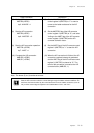
(10) Start the A/D conversion.
ANCTR2 (x'3FB2')
bp7 : ANST = 1
(11) Complete the A/D conversion.
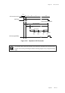
Description
Note : The above (3) to (4) can be set at once.
Even if the external interrupt 3 is generated during A/D conversion, the A/D converter is
operated in normal. Also, once the A/D conversion is finished, it is never started again.