


Chapter 6 8-bit Timers
VI - 42
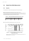
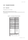
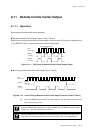
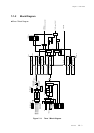
Cascade Connection
TM1BC + TM0BC counts up from x'0000' as a 16-bit timer. When TM1BC + TM0BC reaches the set
value of TM1OC + TM0OC register, the timer 1 interrupt request flag is set to "1" at the next count
clock, and the value of TM1BC + TM0BC becomes x'0000' and counting up is restarted.
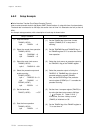
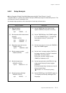
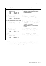
(7) Set the TM0IE flag of the timer 0 interrupt
control register (TM0ICR) to "0" to disable the
interrupt.
(8) Set the interrupt level by the TM1LV1-0 flag of
the timer 1 interrupt control register (TM1ICR).
If any interrupt request flag may be already
set, clear all request flags.
(9) Set the TM1IE flag of the TM1ICR register to
"1" to enable the interrupt.
(10) Set the TM1EN flag of the TM1MD register to
"1" to start timer 1.
(11) Set the TM0EN flag of the TM0MD register to
"1" to start timer 0.
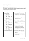
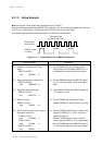
Setup Procedure
(7) Disable the lower timer interrupt.
TM0ICR (x'3FE9')
bp1 :TM0IE = 0
(8) Set the level of the upper timer
interrupt.
TM1ICR (x'3FEA')
bp7-6 :TM1LV1-0 = 10
(9) Enable the upper timer interrupt.
TM1ICR (x'3FEA')
bp1 :TM1IE = 1
(10) Start the upper timer operation.
TM1MD (x'3F55')
bp3 :TM1EN = 1
(11) Start the lower timer operation.
TM0MD (x'3F54')
bp3 :TM0EN = 1
Description
[ Chapter 3 3-1-4. Interrupt Flag Setup ]
Use a 16-bit access instruction to set the (TM1OC + TM0OC) register.
Start the upper timer operation before the lower timer operation.