


Chapter 13 Serial Interface 4
Operation
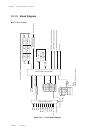
XIII - 11
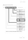
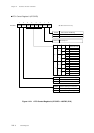
13-3-1 Setup Example of the Slave IIC Serial Interface
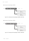
Setup Example of the Data Transmission
This section describes the setup example of slave transmission using serial interface 4.
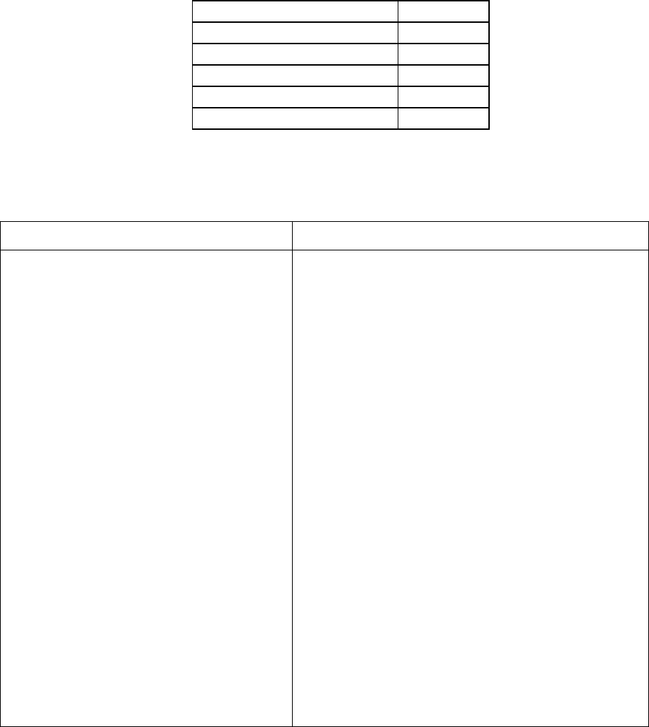
Table 13-3-2 shows the conditions for transmission routine.
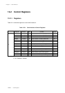
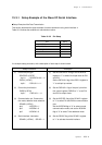
Table 13-3-2 Pin Setup
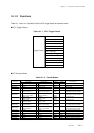
(1) Control the pin type.
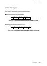
SC4ODC0 (x'3F3F')
bp1-0 : SC4ODC01-00 = 11
P0PLU (x'3F40')
bp2-1 : P0PLU2-1 = 11
(2) Control the pin direction.
P0DIR (x'3F30')
bp2-1 : P0PLU2-1 = 11
(3) Communication pin, Communica-
tion mode, address mode selection
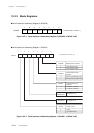
SC4AD1 (x'3FA4')
bp4 : I2CPSEL = 1
bp3 : I2CGEM = 0
bp2 : I2CADM = 0
(4) Serial interface 4 actication
SC4AD1 (x'3FA4') : SELI2C = 1
(1) Set the SC4ODC01-0 flag of the SC4ODC0
register to "1" to select N-ch open drain for P01
and P02.
Set the P0PLU2-1 flag of the P0PLU register to
"1" to add pull-up resistor.
(2) Set the P0PLU2-1 flag of the port 0 pin direc-
tion control register (P0DIR) to "1" to set P01
and P02 to output mode.
(3) Set the I2CPSEL flag of the SC4AD1 register
to "1" to select P01 and P02 for communication
pins.
Set the I2CGEM flag to "0" to select normal
communication mode, and set the I2CADM
flag to "0" to select 7 bits adddress mode.
(4) Set the SELI2C flag of the SC4AD1 register
to "1" to activate the serial interface.
An example setup procedure, with a description of each step is shown below.
Description
Setup Procedure
Item Setup
Data pin (SDA) P01
Clock pin (SCL) P02
Addressing mode 7 bits
Slave address 110011
Transmission data x'55'