


Chapter 18 Flash EEPROM
XVIII - 12
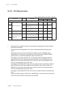
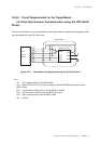
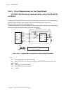
Onboard Serial Interface Programming Mode
xOnboard serial writer (YDC MODEL: AF200)
xFlash programming connectors or pins for target board.
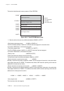
Software requirements
xLoad program installed in the internal flash EEPROM
xProgramming algorithm for operating onboard serial writer
Cautions on onboard serial programming
xPower supply voltage during programming should be within 2.7 V to 3.6 V. If you program outside this
limit, reliability of the written data may be damaged.
xAlways set the pull-up resistors on the target board so that serial interface communication pins does not
become floating state. The pull-up resistors are necessary for the Flash EEPROM not to enter the
programming mode when the serial writer is not connected.
xSerial interface I/O pins used for onboard serial programming should be reserved as dedicated pins to
prevent other user circuits from communicating with the device. Altenatively, design your target board to
be capable of normal communication with serial writer.
x Install the switch that controlls Vpp pin which supplies +5 V during Flash EEPROM programming and
supplies same potential (VDD) during other operations.
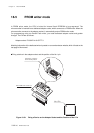
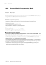
18-6 Onboard Serial Programming Mode
18-6-1 Overview
The onboard serial programming mode is primarily used to program the flash EEPROM in devices that are
already installed on a PCB board with internal serial interface.
Hardware and software requirements
Hardware and software products required for onboard serial programming are as follows.
Hardware requirements