


Chapter 11 Serial Interface 0, 1
XI - 24
Operation
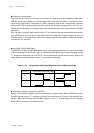
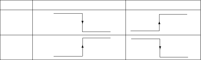
SCnCE1
Received data input edge
Transmission data output edge
1
0
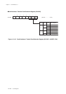
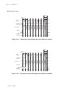
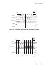
Table 11-3-2 Transmission Data Output Edge and Received Data Input Edge
Input Edge / Output Edge Setup
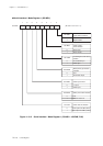
The SCnCE1 to 0 flag of the SCnMD0 register set an output edge of the transmission data, an input edge
of the received data. As the SCnCE1 flag = "0", the transmission data is output at the falling edge, and as
"1", output at the rising edge. As SCnCE1="0", the received data is received at the inversion edge to the
output edge of transmission data, and as "1", stored at the same edge.
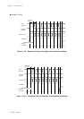
Continuous Communication
This serial has a function for continuous communication. If data is set to the transmission data buffer
TXBUFn during communication, the transmission buffer empty flag SCnTEMP is automatically set to
communicate continuously. Data setup to TXBUFn should be done till the communication complete
interrupt SCnTIRQ is generated after the former data is set. At master communication, there is a sus-
pension of communication for 3 transfer clocks till the next transmission clock is output after the SCnIRQ
generation.
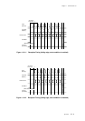
Also, the built-in automatic data transfer fuction ATC can activate. Data can be transfered continuously
up to 255 bytes by ATC activation. In this case, there is a suspension of communication for up to 18
machine cycles + 2.5 transfer clocks. Refer to the transfer mode 8 to 9 in chapter 15, automatic transfer
controller for ATC activation.
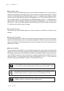
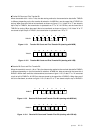
Transmission/reception data polarity switching
Polarity of transmission/reception data can be switched by register setup. When SCnREN flag of the
SCnMD0 register is set to "1", inverted input signal from data input pin is input to the reception shift
register. When SCnTRN flag of the SCnMD0 register is set to "1", inverted signal set in the transfer
buffer TXBUFn is output to the data output pin.