


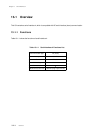


Chapter 13 Serial Interface 4
Operation
XIII - 10
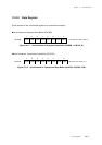
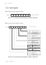
Busy Flag
This serial interface contains 2 busy flags (SLVBSY, I2CBSY).
The SLVBSY flag is set to "1" when address transmitted from master matches with the slave address.
The I2CBSY flag is set to "1" during communication on IIC bus.
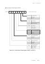
In 10 bits addresss mode, if the upper 2 bits address which is first to be transmitted from master matches
with the I2CAD9-8 of the SC4AD1 register, the SLVBSY flag is set to "1" and SC4IRQ is not generated.
If the lower 8 bits address which is next to be transmitted from master matches with the I2CAD7-0 of the
SC4AD0 register, the SLVBSY flag is remained to "1" and SC4IRQ is generated. If these address mis-
match, the SLVBSY flag is cleared to "0" and SC4IRQ is not generated.
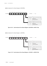
Bus Line Monitor
Bus line can be monitored during the general call communicaation.
For monitoring, while the SELI2C flag is set to "1", set the I2CGEM flag of the SC4AD1 register to "1" and
set the direction control of the communication pin to input. Though serial 4 interrupt is generated at this
time, it does not output signal to the data and clock, and thus, has no effect on the communicaiton.
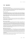
Pin Setup
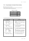
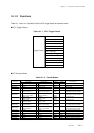
Table 13-3-1 shows pin setup (SDA, SCL pins) for serial interface 4 data transmission.
N-ch open drain setup is always necessary for using this serial interface. Use the pull-up resistor control
register (PnPLU) of each port for pull-up resistor setup. Input/output of the transfer data is automatically
switched.
Table 13-3-1 Pin Setup
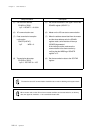
Note that this serial interface does not features the functions which resets the serial interface
circuit on determination of reception data or change the slave address. Always use the soft-
ware for determination of reception data incuding in the general call communication mode.
Item Data I/O pin Clock I/O pin
SDA pin SCL pin
P01 P02
Function P53 P54
Port pin
Nch open-drain control register
Pull-up resistor control register
SC4ODC0
SC4ODC1
P0PLU
P5PLU