


XI - 45
Chapter 11 Serial Interface 0, 1
Operation
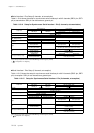
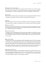
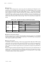
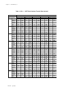
Parity bit is to detect wrong bits with transmission / reception data.
Table 11-3-20 shows kinds of parity bit. The SCnNPE, SCnPM1 to 0 flag of the SCnMD2 register set
parity bit.
Break Status Transmission Control Setup
The SCnBRKE flag of the SCnMD2 register generates the break status. If SCnBRKE is set to "1" to
select the break transmission, all bits from start bits to stop bits transfer "0".
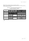
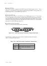
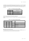
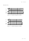
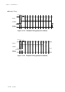
The SCnFM1 to 0 flag of the SCnMD2 register sets the frame mode. Table 11-3-19 is shown the UART
Serial Interface Frame Mode setting. If the SCnCMD flag of the SCnMD1 register is set to "1", and UART
communication is selected, the transfer bit count on the SCnLNG2 to 0 flag of the SCnMD0 register is no
more valid.
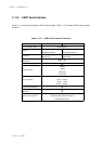
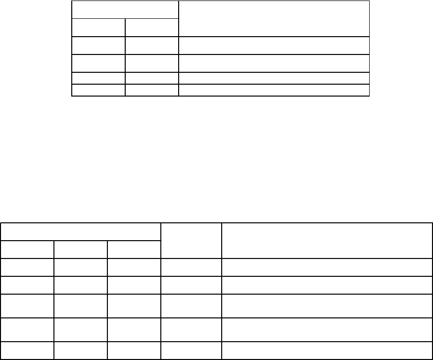
Table 11-3-20 Parity Bit of UART Serial Interface
Table 11-3-19 UART Serial Interface Frame Mode
SCnFM1 SCnFM0
0 0 Character bit 7 bits + Stop bit 1 bit
0 1 Character bit 7 bits + Stop bit 2 bits
1 0 Character bit 8 bits + Stop bit 1 bit
1 1 Character bit 8 bits + Stop bit 2 bits
SCnMD2 register
Frame mode
SCnNPE SCnPM1 SCnPM0
0 0 0 fixed to 0 Set parity bit to "0".
0 0 1 fixed to 1 Set parity bit to "1".
0 1 0 odd parity
Control that the total of "1" of parity bit and character
bit should be odd.
0 1 1 even parity
Control that the total of "1" of parity bit and character
bit should be even.
1 - - none Do not add parity bit.
SCnMD2 register
Parity bit Setup