


Chapter 12 Serial Interface 3
Operation
XII - 38
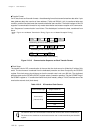
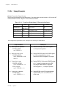
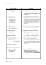
(13) Select the transfer clock.
SC3MD1 (x'3FA9')
bp2 : SC3MST = 1
(14) Control the pin function.
SC3MD1 (x'3FA9')
bp4 : SC3SBOS = 1
bp5 : SC3SBIS = 1
bp6 : SC3SBTS = 1
bp7 : SC3IOM = 1
(15) Set the interrupt level.
SC3ICR (x'3FF9')
bp7-6 : SC3LV1-0 = 10
(16) Enable the interrupt.
SC3ICR (x'3FF9')
bp1 : SC3IE = 1
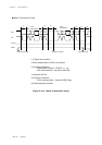
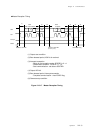
<Transmission is started.>
(17) Start serial transmission.
Confirm that SCL (P52) is "H".
Transmission data
→ SC3TRB (x'3FAB')
<Transmission is completed.>
<Setup for the next data transmission>
(18) Judge the monitor flag.
SC3CTR (x'3FAA')
bp6 : SC3STC
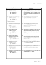
(13)
Set the SC3MST flag of the SC3MD1 register to
"1" to select clock master (internal clock).
At IIC communication, external clock should not
be selected.
(14) Set the SC3SBOS, SC3SBIS, SC3SBTS flags of
the SC3MD1 register to "1" to set the SDA pin
(the SBO3 pin) to serial data output, the SBI3 pin
to serial data input, and the SCL pin (the SBT3
pin)to serial clock I/O. Set the SC3IOM flag to "1"
to set "serial data input from the SDA pin (the
SBO3 pin)".
(15) Set the interrupt level by the SCLV1-0 flag of the
serial 3 interrupt control register (SC3ICR).
(16) Enable the interrupt to the SC3IE flag of the
SC3ICR register. If the interrupt request flag
(SC3IR of the SC3ICR register) is already set,
clear SC3IR before the interrupt is enabled.
(17) Set the transmission data to the transmit/
receive shift register SC3TRB. Then the
transfer clock is generated to start transmission.
If the ACK bit is received after data transmission,
the communication complete interrupt SC3IRQ is
generated.
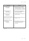
(18) Confirm the SC3STC flag of the serial 3 control
register (SC3CTR). When the former
transmission is completed in normal, SC3STC =
"0". If SC3STC = "1", the communication should
be operated again.
[ Chapter 3 3-1-4. Interrupt Flag Setup ]
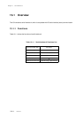
Setup Procedure Description