II - 21
Chapter 2 CPU Basics
Standby Functions
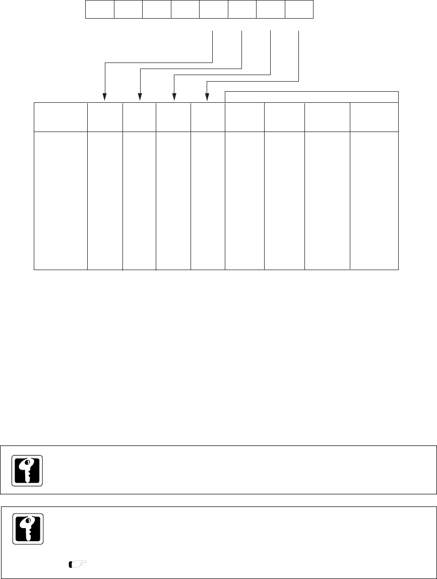
Figure 2-4-2 Operating Mode and Clock Oscillation (CPUM : x'3F00', R/W)
2-4-2 CPU Mode Control Register
Transition from one mode to another mode is controlled by the CPU mode control register (CPUM).
7
0
CPUM
00
0
STOP HALT OSC1
OSCSEL1
SOSCDBL
OSCSEL0 OSCDBL
OSC0
Operation
mode
NORMAL
IDLE
SLOW
HALT0
HALT1
STOP0
STOP1
0
0
0
0
0
1
1
0
0
0
1
1
0
0
0
0
1
0
1
0
1
0
1
1
0
1
0
1
STOP HALT OSC1 OSC0
OSC1
/OSC0
XI/XO
System
clock
Oscillation
Oscillation
Halt
Oscillation
Halt
Halt
Halt
Oscillation
Oscillation
Oscillation
Oscillation
Oscillation
Halt
Halt
At reset :
CPU
Operating
Operating
Operating
Halt
Halt
Halt
Halt
00
0
0
5
6
34
2
1
0
Status
OSCI
XI
XI
OSCI
XI
Halt
Halt
The procedure for transition from NORMAL to HALT or STOP mode is given below.
(1) If the return factor is a maskable interrupt, set the MIE flag in the PSW to "1" and set the interrupt
mask (IM) to a level permitting acceptance of the interrupt.
(2) Clear the interrupt request flag (xxxIR) in the maskable interrupt control register (xxxICR) , set the
interrupt enable flag (xxxIE) for the return factor, and set the IE flag in the PSW.
(3) Set CPUM to HALT or STOP mode.
Set the IRWE flag of the memory control register (MEMCTR) to clear interrupt request flag
by software.
System clock (fs) is changed depending on CPU operation mode.
In NORMAL mode, HALT0 mode, fs is based on fosc (high speed oscillation). In SLOW
mode, IDLE mode, HALT1 mode, fs is based on fx (low speed oscillation).
[ Chapter 2. 2-5 Clock Switching ]


