


Chapter 12 Serial Interface 3
Operation
XII - 31
At communication, set Nch-open drain for pin's type, because the hardware switches if bus is
used/released. And even at reception, select the SDA pin (the SBO3 pin) direction control to
"output".
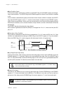
Transmission/Reception Mode Setup and Operation
The SC3REX flag of the SC3CTR register selects the status of the transmission or the reception. The
first data is always added start condition for communication. The start condition is output from the mas-
ter, this serial.
If the communication is continued (no stop condition is generated), start condition should not be added
from the next data. At this case, start condition is set to be disabled in the interrupt service routine after
the first data communication is finished. At addressing format, slave address and R/W bit are set to the
first data after start condition for transmission.
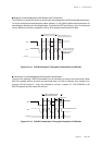
At master reception, switch to the reception mode at the interrupt transaction after the transmission of
the first 1 byte data is finished, after the ACK signal from slave is confirmed. If the communication should
be continued to other device without stop, transmit slave address and R/W bit again after start condition
is generated again. At reception, the SDA line is automatically released to wait for reception. After the
storage of data is finished, confirmation of the reception (ACK bit) is output.
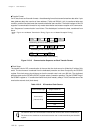
IICBUSY Flag Operation
As data is set to the transmit/receive shift register SC3TRB, the IICBSY flag of the SC3CTR register is
set to "1". The IICBSY flag is cleared by software. As the IICBSY flag is cleared, the stop condition is
automatically generated to complete the communication.
If start condition is detected during communication, the communication complete interrupt SC3IRQ is
generated, then the IICBSY flag is automatically cleared.
Seaquence Communication
At IIC communication, not the same to the clock synchronous serial communication, the seaquence
communication with built-in automatic transfer controller ATC1, is not available.
The following items are the same to the clock synchronous serial. Refer to the following pages.
First Transfer Bit Setup
Refer to : XII-11
Transmit, Reception Data Buffer
Refer to : XII-11
Transfer Bit Count and First Transfer Bit
Refer to : XII-11
Communication Forced Reset
Refer to : XII-13
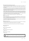
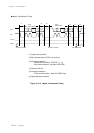
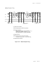
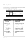
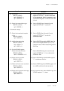
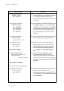
[ Figure 12-3-16 Master Transmission Timing, Figure 12-3-17 Master Reception Timing ]