


Chapter 13 Serial Interface 4
Operation
XIII - 9
13-3 Operation
Activation and Termination Factors
Set the SELI2C flag of the SC4AD1 register to "1" to activate this serial interface. For the termination, set
the flag to "0". The ports used for communication can be used as general-purpose port while the serial
interface is not in operative state. When the SELI2C register is set to "0", SC4AD0 register, SC4TXB
register and SC4RXB register is automatically cleared.
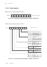
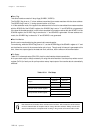
Slave Address Setup
This serial interface can seletct either 7 bits or 10 bits slave address. To select 7 bits slave address, set
the I2CADM flag of the SC4AD1 register to "0" to select 7 bits address mode, and set the slave address to
upper 7 bits of the SC4AD0 register (I2CAD7 to I2CAD1). To select 10 bits slave address, set the I2CADM
flag of the SC4AD1 register to "1" to select 10 bits address mode, and set the upper 2 bits of the slave
address to lower 2 bits of the SC4AD1 register (I2CAD9, I2CAD8) and set the lower 8 bits of the slave
address to SC4AD0 register.
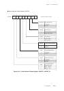
General Call Communitacion
This serial interface is compatible with general call communication mode. Set the I2CGEM flag of the
SC4AD1 register to "1" to select general call communication mode. In this mode, slave address set in the
SC4AD0 and SC4AD1 registers are invalid.
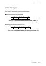
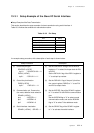
Data Transmission/Reception
This serial interface enables automatic address determination after detection of start condition on IIC
bus. Serial interface 4 interrupt (SC4IRQ) is generated only when address transmitted from master
matches with the set slave address. Data transmission/reception are controlled with the WRS flag of the
SC4STR register, and slave transmission is selected when the WRS flag is set to "0", slave reception is
selected when the WRS flag is set to "1". In slave transmission, setting the transmission data to SC4TXB
register opens the bus line and data transmission is started by the clock transmitted from master. In
slave reception, setting the dummy data to SC4RXB register opens the bus line and data reception is
started by the clock transmitted from master.
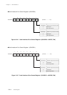
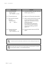
Start/Re-Start Condition Detection
When data (SDA) pin changes from "H" to "L" while clock (SCL) pin is "H", start condition is detected and
the STRT flag of the SC4STR register is set to "1". The STRT flag is cleared to "0" after communication data
is set when the interrupt routine right after the slave address reception sets the communication data. If start
condition is detected again during data transferring, the RSTRT flag is set. This flag is cleared to "0" after
communication data is set when the interrupt routine right after the slave address reception sets the com-
munication data.
If address transmitted from master does not match with the slave address, these flags are automatically
cleared at the timing when address miscompare is detected.