


I - 15
Chapter 1 Overview
Pin Description
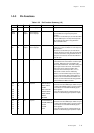
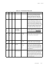
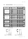
Table 1-3-7 Pin Function Summary (5/6)
Name No. I/O Function Other Function Description
BUZZER 21 Output Buzzer output P06 Piezoelectric buzzer driver pin. The driving
frequency can be selected by the DLYCTR
register. Select output mode by the P0DIR
register and select P06 buzzer output by the
DLYCTR register. When not used for buzzer
output, this pin can be used as a normal I/O pin.
TCI07 26 I/O Timer I/O pin P14 Event counter clock input pin, overflow pulse and
PWM signal output pin for 16-bit timer 7. To use
this pin as event clock input, configure this as
input by the P1DIR register. In the input mode,
pull-up resistors can be selected by the P1PLU
register. For overflow pulse, PWM signal output,
select the special function pin by the port 1 output
mode register (P1OMD), and set to the output
mode by the P1DIR register. When not used for
timer I/O, this can be used as normal I/O pin.
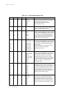
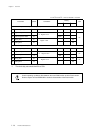
VREF+ 6
-
+ power supply for
A/D converter
VREF- 61 - - power supply for
A/D converter
AN0 62 Input Analog input pins PA0, DA0
AN1 63 PA1, DA1
AN2 64 PA2
AN3 1 PA3
AN4 2 PA4
AN5 3 PA5
AN6 4
PA6
DA0 62 Output Analog output pins PA0, AN0
DA1 63 PA1, AN1
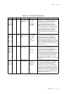
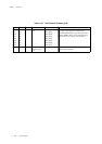
IRQ0 27 Input P20
IRQ1 28 P21, ACZ
IRQ2 29 P22
IRQ3 30 P23
IRQ4 31 P24
ACZ 28 Input AC zero-cross
detection input pin
P21, IRQ1 An input pin for an AC zero-cross detection circuit.
The AC zero-cross detection circuit outputs a high
level when the input is at an intermediate level. It
outputs a low level at all other times. ACZ input
signal is connected to the P21 input circuit and
the IQR1 interrupt circuit. When the AC zero-cross
detection circuit is not used, this pin can be used
as a normal P21 input.
External interrupt
input pins
Analog output pins for an 2-channel, 8-bit D/A
converter. When not used for analog output,
these pins can be used as normal I/O pins.
Reference power supply pins for the A/D
converter. Normally, the values of VDD=VREF+
and VSS=VREF- are used. When they are not
used, the values should be VREF+=VDD and
VREF-=VSS.
Analog input pins for an 7-channel, 10-bit A/D
converter. When not used for analog input, these
pins can be used as normal I/O pins.
External interrupt input pins. The valid edge for
IRQ0 to 4 can be selected with the IRQnICR
register. IRQ1 is an external interrupt pin that is
able to deternine AC zero crossings. Both edge
for IRQ0 to 4 are valid for interrupt. When these
are not used for interrupts, these can be used as
normal input pins.