XV - 5
Chapter 15 A/D Converter
Control Registers
15-2-2 Control Registers
A/D Converter Control Register 0 (ANCTR0)
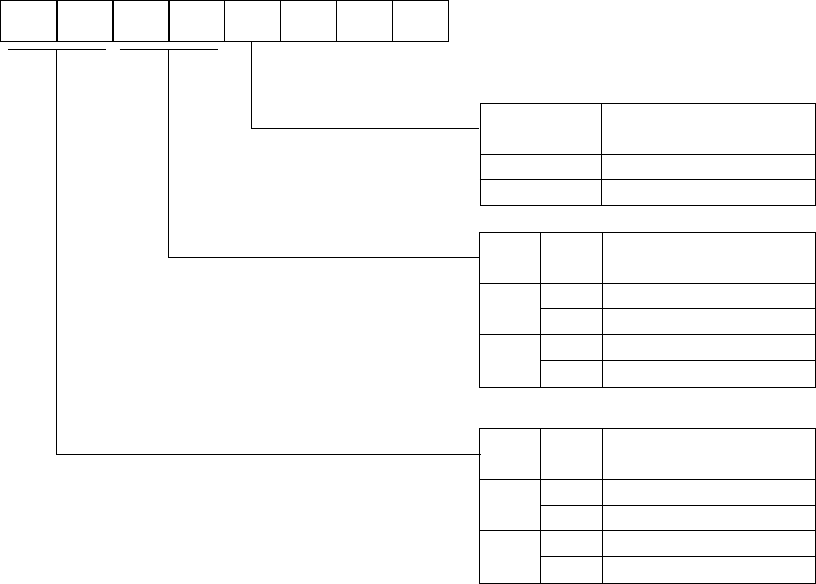
Figure 15-2-1 A/D Converter Control Register 0 (ANCTR0 : x'03FB0', R/W)
0
as 800 ns < T
AD ≤ 15.26 µs
1
0
1
0
1
A/D conversion clock (ftad=1/TAD)
01245673
ANCTR0
---
ANLADE
ANLADE
ANCK0ANCK1
ANCK0ANCK1
ANSH1 ANSH0
ANSH0ANSH1
0
1
A/D ladder resistance control
A/D ladder resistance OFF
A/D ladder resistance ON
fs/2
fs/4
fs/8
fx × 2
0
1
0
1
0
1
Sample and hold time
TAD × 2
T
AD × 6
T
AD × 18
Reserved
(At reset : 0 0 0 0 - - - )
Sampling and holding time is decided by
the input impedance at analog input.
T
AD means the cycle for A/D conversion clock.
*
*


